f) display hinge cover
g) keyboard
h) hard drive
i) optical drive
j) memory
k) base cover
l) battery
m) express card
n) SD card
7. Follow the procedures in
After Working Inside Your Computer
.
Removing the Power Connector
1. Follow the procedures in
Before Working Inside Your Computer.
2. Remove the:
a) SD card
b) express card
c) battery
d) base cover
e) memory
f) optical drive
g) hard drive
h) keyboard
i) display hinge cover
j) palmrest
k) system board
l) display assembly
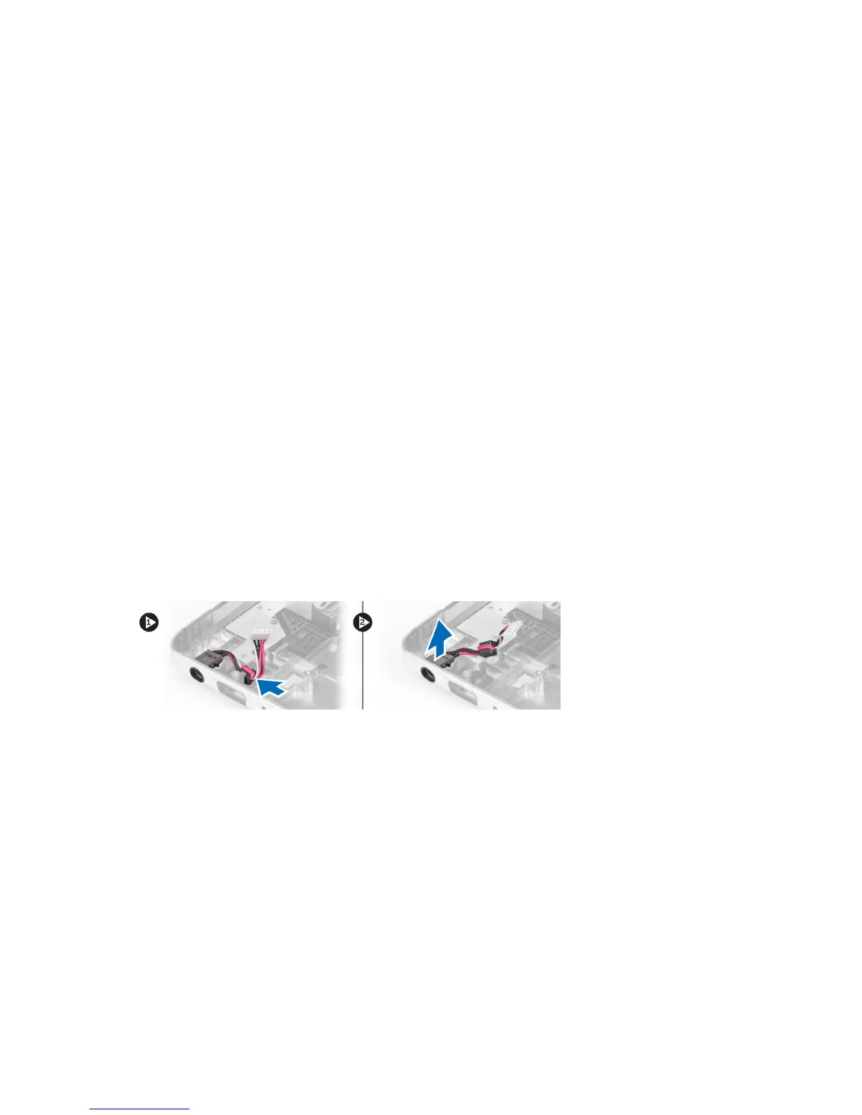
3. Push the ferrite bead through the notch and lift up to remove the power connector.
Installing the Power Connector
1. Place the power connector in its location on the base of the chassis.
2. Install the:
a) display assembly
b) system board
c) palmrest
d) display hinge cover
e) keyboard
f) hard drive
g) optical drive
h) memory
i) base cover
44
 Loading...