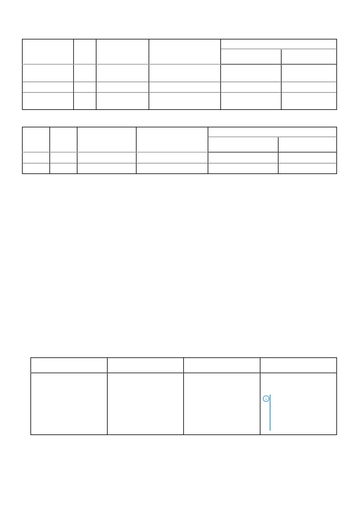
DIMM type Rank Capacity DIMM rated voltage and
speed
Operating Speed
1 DIMM per channel 2 DIMMs per
channel
RDIMM 2 R 16 GB, 32 GB, 64
GB
DDR4 (1.2 V), 3200 MT/s 3200 MT/s 3200 MT/s
LRDIMM 4 R 128 GB DDR4 (1.2 V), 3200 MT/s 3200 MT/s 3200 MT/s
Intel persistent
memory (BPS)
2R 128 GB, 256 GB,
512 GB
DDR4 (1.2 V), 3200 MT/s 3200 MT/s 3200 MT/s
The following table describes the supported memory matrix of VxRail S670:
DIMM
type
Rank Capacity DIMM rated voltage and
speed
Operating Speed
1 DIMM per channel 2 DIMMs per
channel
RDIMM 2 R 16 GB, 32 GB, 64 GB DDR4 (1.2 V), 3200 MT/s 3200 MT/s 3200 MT/s
LRDIMM 4 R 128 GB DDR4 (1.2 V), 3200 MT/s 3200 MT/s 3200 MT/s
General memory module installation guidelines
To ensure optimal performance of your system, observe the following general guidelines when configuring your system memory.
If your system's memory configurations fail to observe these guidelines, your system might not boot, stop responding during
memory configuration, or operate with reduced memory.
The memory bus operates at a speed of 3200 MT/s depending on the following factors:
● System profile selected. For example, Performance Optimized, or Custom (can be run at high speed or lower).
● Maximum supported DIMM speed of the processors.
● Maximum supported speed of the DIMMs.
MT/s indicates DIMM speed in MegaTransfers per second.
The memory bus supports Fault Resilient Memory-Non Uniform Memory Access.
The system supports Flexible Memory Configuration, enabling the system to be configured and run in any valid chipset
architectural configuration. The following are the recommended guidelines for installing memory modules:
● All DIMMs must be DDR4.
● x4 and x8 DRAM based memory modules can be mixed.
● If memory modules with different speeds are installed, they operate at the speed of the slowest installed memory module(s).
● Populate memory module sockets only if a processor is installed. For dual-processor systems, sockets A1 to A16 and sockets
B1 to B16 are available.
● In Optimizer Mode, the DRAM controllers operate independently in the 64-bit mode and provide optimized memory
performance.
● The following table describes the memory population rules:
Processor
Configuration Memory population Memory population
information
Dual processor (Start with
processor1. Processor 1
and processor 2 population
should match)
Optimizer (Independent
channel) population order
A{1}, B{1}, A{2}, B{2}, A{3},
B{3}, A{4}, B{4}, A{5}, B{5},
A{6}, B{6}, A{7}, B{7} A{8},
B{8}, A{9}, B{9}, A{10},
B{10}, A{11}, B{11}, A{12},
B{12}, A{13}, B{13}, A{14},
B{14}, A{15}, B{15}, A{16},
B{16}
2, 4, 8, 12, 16, 24 and 32
DIMMs are supported per
system.
NOTE: Optimizer
population order is not
traditional for 8 and 16
DIMMs installations for
dual processor.
● Populate all the sockets with white release tabs first, followed by the black release tabs.
● Memory modules of different capacities can be mixed provided other memory population rules are followed.
22
Replacement of hardware components