Delta Controls
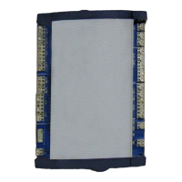
Access Door Module Page 7 of 26
INDICATORS
LED Function Description
AC PWR OK AC Power Indicator
This green LED is on when the 24 VAC Power is
present on the device. If no 24 VAC Power
transformer is connected or the fuse (F1) is blown,
the LED will be off.
Network
(NET1)
RS-485 Communication Status
Indicators for NET1 (LINKnet)
Green LEDs flash to indicate when the device is
transmitting data through the associated port, and
red LEDs flash to indicate when the device is
receiving data through the port.
Outputs
(OP1 – OP9)
Each green Output LED displays the
status of its corresponding output
The green LED is on or off to match the binary
status of the associated output.
CONTROLLER ADDRESS DIP SWITCHES
Each individual DIP switch represents a pre-defined value (as printed on PCB beside the address block),
which added together forms the device address. LINKnet device addresses must be between 1 and 12 for the
device to communicate with its’ master device. Each LINKnet device must have a unique device address in
this range.
OUNTING
The Access Door Module is designed for quick and easy mounting in a number of locations. Normally this
should be within a secured enclosure.
A tamper switch should always be wired to the Access Door Module, indicating when someone enters the
enclosure and tampers with the Access Door Module. Any standard switch that will mount inside the
enclosure can be used. The tamper switch can be wired so that the circuit is monitored using an EOL circuit
(see Input Wiring below for details).