Delta Controls
Document Edition 3.1
Page 19 of 35
NOTES: For fan-powered boxes, series fans should always be configured for continuous
operation – never intermittent or the fan could run backwards on startup. When a
parallel fan is used in a heating application it should be configured as the 1st stage of
heating (and wired to the appropriate output accordingly), rather than as a fan output.
Setup Parameters
Setup Variable Function Notes
AV24 Tri-state Flow Damper Runtime Default of 120 seconds
AV25 Air Flow Factor Converts Duct size and Air flow
velocity to CFM or Liters/Second
AV26 Air Flow Minimum Minimum Air Flow Setpoint
AV27 Air Flow Maximum Maximum Air Flow Setpoint
AV28 PWM minimum value or Binary On Delay
(or Binary Off Delay for a Fan)
Depends on OP3 configuration
AV29 PWM maximum value or Time
Proportioned Heating Controller Limit
Depends on OP3 configuration
Sequence of Operation
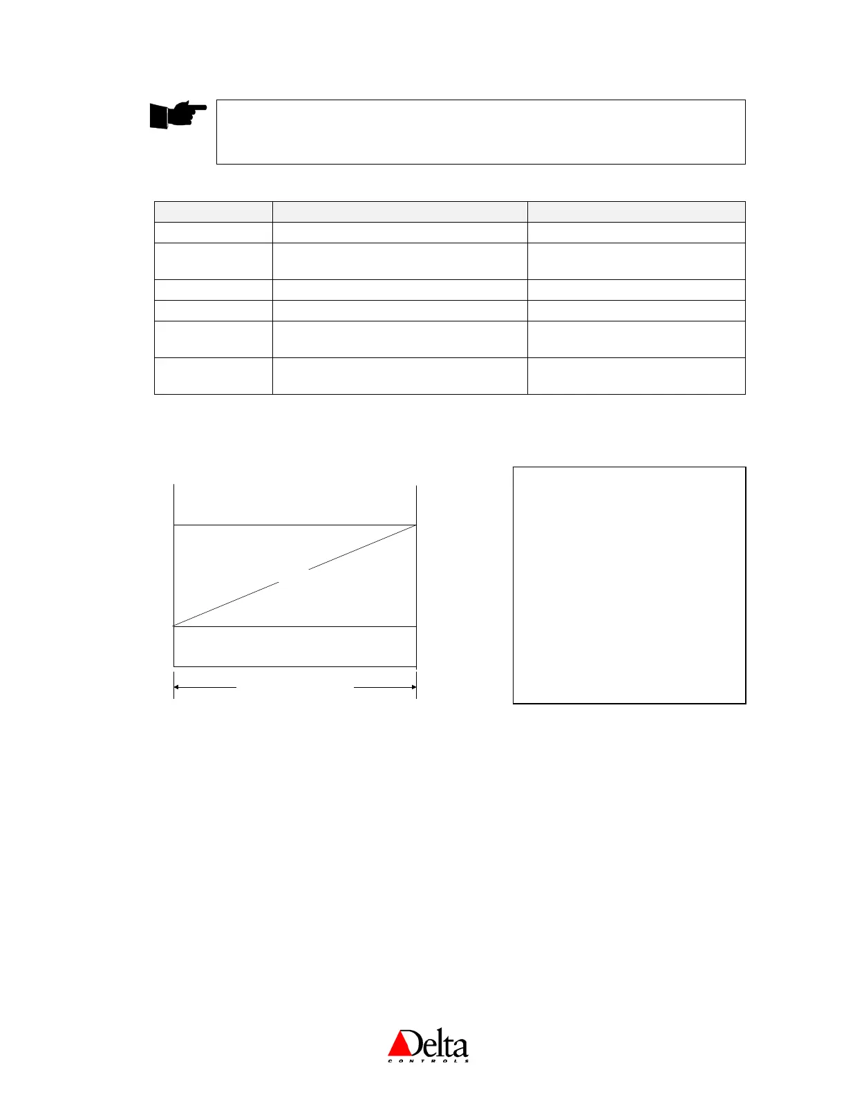
The air flow setpoint is generated from the Cooling Minimum setpoint, Cooling Maximum Setpoint and the Cool
1 value as shown below.
Air flow Setpoint
Max
Cooling flow
Min
Cooling flow
Controller Output (Cooling 1)
0
Max Flow
0% 100%
The Air Flow input is compared to the current Airflow setpoint by the flow control loop. On the DNT-T103, the
Tri-State damper outputs 1 and 2 are used to control the damper to adjust the flow to match the current airflow
setpoint. The rate of the damper from closed to open is adjusted using AV24 – Damper Run Time. The default
value is 120 seconds. On the DNT-T221, the analog damper output 1 is used to control air flow, but also requires
that an appropriate runtime be set for the actuator (via Setup variable AV24).
In Unoccupied Deadband mode the Airflow Setpoint is set to zero.
Output 3 may be selected as a fan for fan-powered boxes. Alternatively, the output may be selected to be Heating
1 or supplementary Cooling 2, which may be of type Binary or PWM or Timed Proportional.
Note that variable AV25 (Air Flow Factor) represents a value that includes duct size and any other constants or
conversion factors so Input 2 reads air flow (in CFM or L/S), and requires that:
• a 0 to 1” H
2
O (0 to 248.8 Pa) sensor is connected to Input 2 (AI2); and
• the air flow units of either CFM or L/S is selected
AFF = box K factor * Area in in
2
/ 144 [which is then divided by 2.1188 to get L/S, if desired]
Also refer to page 13 for information on Box Mode and Controller Operation.
NOTE: So as to prevent a series fan
from starting backwards, the damper
stays shut in all night modes – it does
not modulate. If heating is required
during the night, a radiant panel can
be used to meet the Night Heating
Setpoint (AV10). Since the damper
will not modulate for night cooling
(AV11), if night cooling is required
write a GCL program in an
associated DSC controller on the
network to put the box/BACstat into
Occupancy mode and bring on the air
system until the setpoint is achieved.
 Loading...