Chapter 4 Macro Function|ScrEdit Software User Manual
Revision Apr. 30th, 2007, 2007PDD23000002 4-39
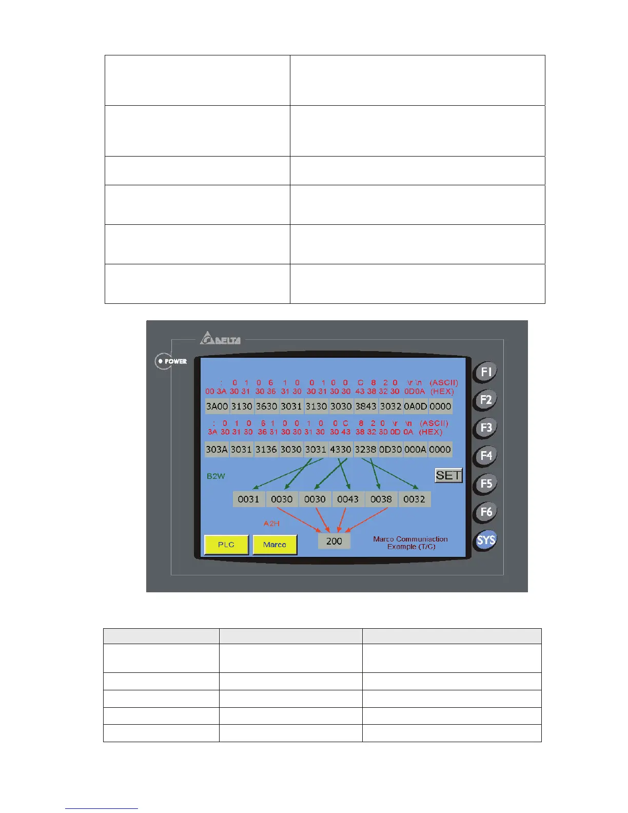
$1001 = 3A00H Set starting Bit. Because the value of high byte and low
byte will be exchanged when HMI sends command, even
though the starting Bit is 3A when sending data, it is
needed to input 3A00.
$1009 = 0A0DH Set end Bit. Because the value of high byte and low byte
will be exchanged when HMI sends command, even
though the end Bit is 0D0A when sending data, it is
needed to input 0A0D.
$1500 = PUTCHARS($1001, 20, 500) Start to send data from $1001, the data length is 20
bytes and the timeout setting is 500ms.
$1501 = GETCHARS($1121, 20, 500) Receive the PLC response data after communication.
The received data is stored in $1121, the data length is
20 bytes and the timeout setting is 500ms.
$1050 = B2W($1125, 6) Decompose received ACSII code into one BYTE and
one BYTE from $1125 respectively and convert them
into WORD format.
$1060 = A2H($1051) Then, start to convert the WORD data into the value in
hexadecimal format from $1051 and display the result in
decimal format on the screen.
Others
Command Equation Descrption
TIMETICK
V1 = TIMETICK
Get the time from system startup to
present
GETLASSERROR
V1 = GETLASTERROR
Get last error value
#
#V1
Comment
delay
delay V1
System delay
GETSYSTEMTIME
V1 = GETSYSTEMTIME
Get system time