QUICK START SM3300
9 / 11 DELTA ELEKTRONIKA B.V. rev. June 2022
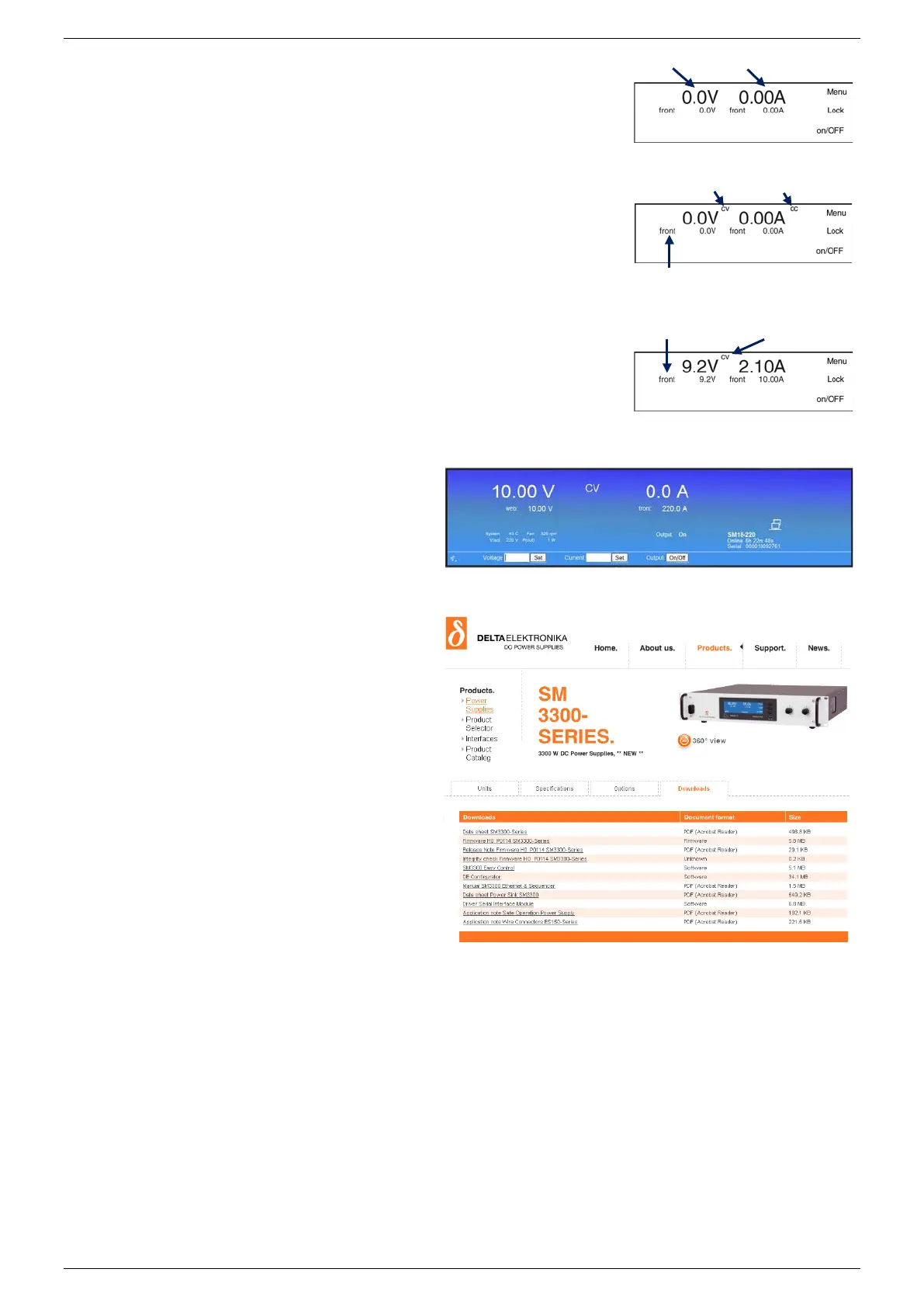
• The first line in the front display indicates the actual output voltage and current.
The second line shows the settings of the controls.
• Check the text 'front' is indicated - this means the unit is in local-operation and
can be controlled by the V-knob and A-knob at the front panel.
• Switch the output on by pressing the on/OFF button.
• Turn the V- and A-knob a half turn clockwise. Depending on the load, a voltage
should now be present on the output and a current will run through the load.
• Depending on the load and settings, the unit will be either in constant voltage or
constant current mode, respectively CV- or CC-mode.
• Respectively the indication 'CV' will appear on the first line, next to the actual
voltage value. The indication 'CC' will appear next to the actual current value.
LIMITATION OF SETTINGS
• By default, the settings for CV and CC Limit are set to the maximum.
• Change the limit settings via Menu > Protection > Limits.
REMOTE PROGRAMMING
• By default a unit is in local operation, see fig. 4 - 4.
• In remote operation different programming options are available such as 'eth',
'web', 'seq', 'slot1', etc.
•
Via the front menu the source can be set to the required programming input via:
Menu > Configuration > Source.
• When connected to LAN, enter the unit's IP-address in a web browser to open
the web interface.
• With this interface all above described
parameters plus additional parameters can be set
and read.
• For more information, see the chapter Remote
Programming of the user manual.
Download User Manual
FULL VERSION
Check at www.DeltaPowerSupplies.com for
the full version of the user manual via:
Products > SM3300 > Downloads.
Driver & Example Software
APPLICATIONS & INTERFACES
• Check at www.DeltaPowerSupplies.com for
driver and example software via:
Products > SM3300 > Downloads.
Note:
It is strongly recommended to regularly check for updates
for additional functionality and improvements.
fig 4 - 4 Output power is 19W.
fig 4 - 5
The front console of the web interface for setting of the output
and monitoring various parameters.
fig 4 - 6 Regularly check for new versions of
user manual and firmware.
actual voltage actual current
indicator for CV-mode, for CC-mode
fig 4 - 3 Start up settings.
 Loading...


