PMAC Quick Reference Guide
26 Installing and Configuring PMAC
Motor Signals Connections
Incremental Encoder Connection
Each JMACH connector provides two +5V outputs and two logic grounds for powering encoders and
other devices. The +5V outputs are on pins 1 and 2; the grounds are on pins 3 and 4. The encoder signal
pins are grouped by number: all those numbered 1 (CHA1, CHA1/, CHB1, CHC1, etc.) belong to encoder
#1. The encoder number does not have to match the motor number, but usually does. If the PMAC is not
plugged into a bus and drawing its +5V and GND from the bus, use these pins to bring in +5V and GND
from the power supply.
Connect the A and B (quadrature) encoder channels to the appropriate terminal block pins. For encoder
1, the CHA1 is pin 25, CHB1 is pin 21. If using a single-ended signal, leave the complementary signal
pins floating -- do not ground them.
However, if single-ended encoders are used, check the settings of the jumpers E18 to E21 and E24 to E27.
For a differential encoder, connect the complementary signal lines -- CHA1/ is pin 27, and CHB1/ is pin
23. The third channel (index pulse) is optional; for encoder 1, CHC1 is pin 17, and CHC1/ is pin 19.
Checking the Encoder Inputs
Once the encoders have been properly wired, it is important to check its functionality and its polarity.
Note:
Make sure the motor is not powered while performing this test.
In the PEWIN, open a Position window by pressing Alt+V and P from the terminal window. Rotate the
encoder to monitor the corresponding position value of the motor in the Position window. Make sure that
a rotation in the positive direction increments the position values. Also, make sure that the number of
counts per revolution of the encoder matches the number read by PMAC when a complete revolution of
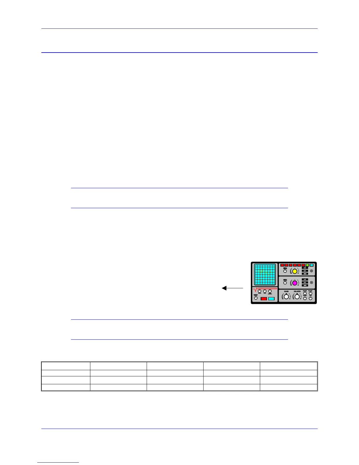
the motor has been rotated. If necessary, for troubleshooting purposes, place an oscilloscope in the
encoder inputs to check the appropriate signals provided by the encoder:
Example for Encoder #1:
• Channel A in pin 25 of JMACH1 (Acc-8D or Acc-8P)
• Channel B in pin 21 of JMACH1 (Acc-8D or Acc-8P)
• Ground in pin 3 or 4 of JMACH1 (Acc-8D or Acc-8P)
Checking the DAC Outputs
Before connecting the DAC outputs to the amplifier, it is opportune to check the DAC outputs operation.
Note:
Make sure the amplifier is not connected while performing this test.
In the PEWIN terminal window, define the following M-Variables for the DACs of the motors under
consideration:
Motor #1 Motor #2 Motor #3 Motor #4
DAC output M102->Y:$C003,8,16,S M202->Y:$C002,8,16,S M302->Y:$C00B,8,16,S M402->Y:$C00A,8,16,S
Motor #5 Motor #6 Motor #7 Motor #8
DAC output M502->Y:$C013,8,16,S M602->Y:$C012,8,16,S M702->Y:$C01B,8,16,S M802->Y:$C01A,8,16,S
 Loading...