5
ASSEMBLY INSTRUCTIONS
WARNING: FOR YOUR OWN SAFETY, DO NOT CONNECT THE MACHINE TO THE POWER SOURCE UNTIL THE
MACHINE IS COMPLETELY ASSEMBLED AND YOU HAVE READ AND UNDERSTOOD THE ENTIRE OWNER’S
MANUAL.
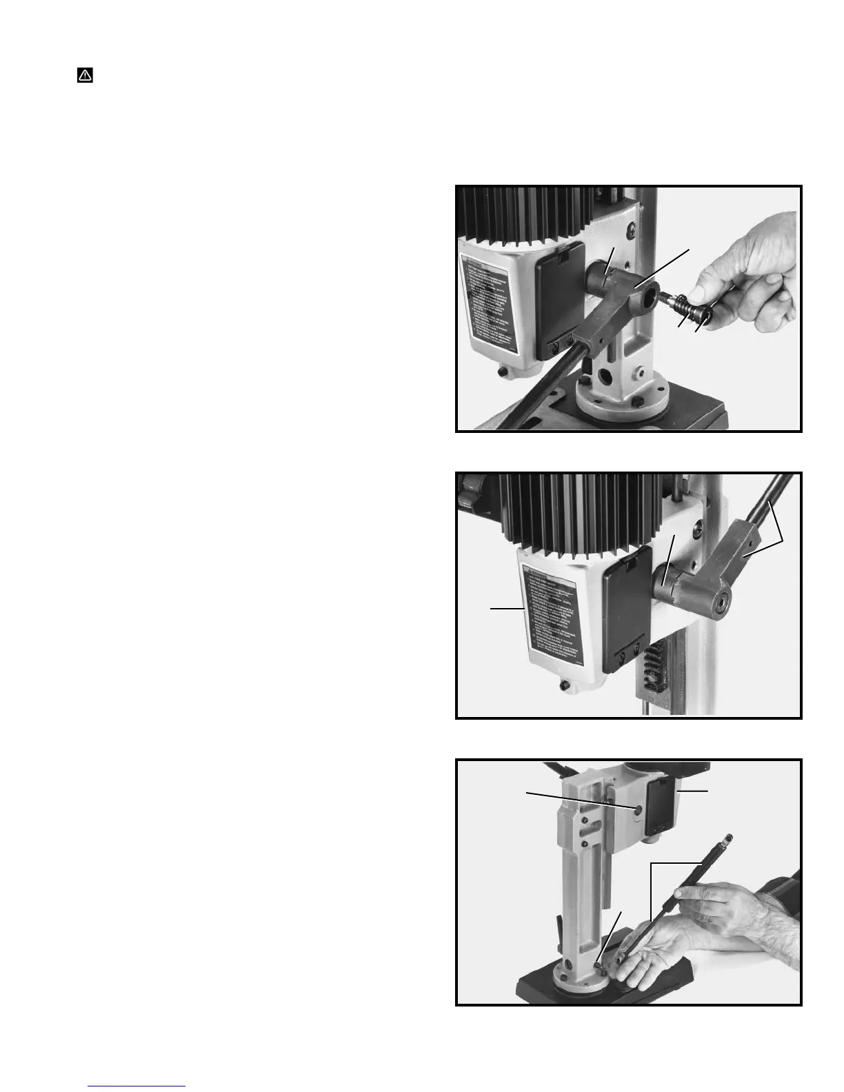
Fig. 3
ASSEMBLING RAISING
AND LOWERING HANDLE
1. Assemble hub of handle assembly (A) Fig. 3, to end
of pinion shaft (B) and fasten handle to pinion shaft
using special screw (C) and spring (D).
Fig. 4
Fig. 5
2. Raise mortising machine head (E) Fig. 4, to the up
position by turning handle (A) clockwise. NOTE: Handle
(A) is spring-loaded and can be repositioned by pulling
out handle and repositioning it on pinion shaft (B).
ASSEMBLING
HYDRAULIC CYLINDER
1. Make sure head (A) Fig. 5, is held in the up position
and assemble the hydraulic cylinder (B) to the two
fittings (C), one located on the column and the other on
the back of the head.
D
C
A
B
B
E
A
A
C
C
B