The document is an instruction manual for the Delta DJ-15 6" Jointer, dated 11-28-95, with part number 1340235. It provides comprehensive information on the jointer's assembly, operation, and maintenance, emphasizing safety throughout.
Function Description:
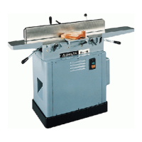
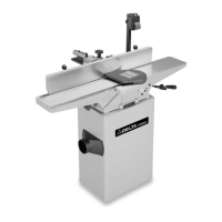
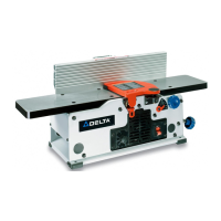
The Delta DJ-15 6" Jointer is a woodworking machine designed for jointing and planing operations.
- Jointing Operations: This involves squaring an edge of a workpiece. The workpiece is positioned on the infeed table with its narrow edge and major flat surface against the fence, then moved across the cutterhead to the outfeed table.
- Planing Operations (Surfacing): Similar to jointing, but the major flat surface of the workpiece is placed on the table with the narrow edge against the fence.
The jointer is used to create flat surfaces, square edges, and bevels on wood, preparing it for further woodworking processes or for joining multiple pieces.
Important Technical Specifications:
- Size: 6" Jointer.
- Electrical Rating:
- Single Phase: 115/230 Volt
- Three Phase: 200-230/460 Volt
- Motor: 3/4 H.P. (for single phase, push-button switch only).
- Wiring Recommendation: #14 wire, fused with a 20 amp, dual element time-lag fuse.
- Cutterhead Rotation: Must be in a clockwise direction when viewed from the left side of the machine, with knives rotating toward the infeed table from the top.
- Maximum Cut Depth: Never make a jointing or planing cut deeper than 1/8".
- Minimum Workpiece Length: Do not perform jointing or planing operations on material shorter than 10 inches.
- Maximum Planing Width: Never perform a planing operation on material wider than 6 inches.
- Minimum Material Thickness for Jointing Short/Thin Pieces: Not less than 1/4" thick.
- Minimum Material Width for Surfacing: At least 3/4" wide.
- Knife Adjustment: Knives are correctly adjusted when the cutting edge extends out 0.015" from the diameter of the cutterhead.
Usage Features:
- Stand and Electricals: The jointer can be purchased with a factory-mounted and wired stand, or it can be fastened to a supporting surface (bench) using four threaded holes in the jointer base. An opening for chip removal and belt clearance is required if mounted on a bench.
- Fence Assembly and Operation:
- The fence carriage and sliding bracket are assembled to the jointer base, ensuring the top surface of the fence carriage is level with the outfeed table for smooth fence movement.
- The fence can be moved across the table by loosening a lock lever, sliding it to the desired position, and retightening. A sliding bracket guards the cutterhead behind the fence.
- Fence Tilt: The fence can be tilted to the right or left by loosening a handle, pulling out a plunger, and moving the tilting lever to the desired angle. The handle is spring-loaded and can be repositioned.
- Beveling: When cutting a bevel, tilting the fence toward the table (forming a V-shape with the tables) allows for easier work pressing into the pocket across the knives.
- Rabbeting Ledge Assembly: The rabbeting ledge is assembled to the side of the infeed table, ensuring it is level with the top surface of the infeed table.
- Cutterhead Guard Assembly: The cutterhead guard post is inserted into a hole, and a locking lever is tightened. It's crucial to ensure the guard operates freely without binding.
- Motor Pulley and Belt Assembly: The motor pulley is assembled to the motor shaft, and the drive belt is placed around the cutterhead and motor pulleys. Pulleys must be aligned, and belt tension adjusted for optimal performance (approximately 1" deflection in the center span).
- Start/Stop Switch: Located on the jointer stand panel, with separate buttons for starting and stopping.
- Adjusting Fence Positive Stops:
- 90 Degree Positive Stop: Checked by engaging the plunger in the index collar notch, tightening the lock handle, and using a square against the fence and table. Adjustments involve loosening a set screw and lock handle, tilting the fence to 90 degrees, then retightening. The tilt scale pointer can also be adjusted.
- 45 Degree Inward/Outward Positive Stops: Checked by positioning the fence as far inward/outward as possible, using a combination square. Adjustments involve loosening a lock handle and locknut, turning an adjustment screw until the fence is accurately set at 45 degrees, then retightening.
- Infeed Table Adjustments:
- The infeed table height is adjusted using a lock handle and a raising/lowering hand lever.
- The depth of cut is read from a pointer and scale.
- Positive stops limit the height and depth. It's recommended that the infeed table at its highest point be 1/2mm below the highest point of the knives for a finish or final cut.
- Outfeed Table Adjustments:
- For most jointing operations, the outfeed table must be exactly level with the knives at their highest point of revolution.
- Adjustments are made using a lock handle and a raising/lowering hand lever.
- Positive stops for the outfeed table's upper and lower limits can be adjusted using locknuts and adjustment screws.
- Operation Techniques:
- Hand Placement: At the start of a cut, the left hand holds the work firmly against the front table and fence, while the right hand pushes the work toward the knives. As the cut progresses, the left hand presses down on the work on the rear table, maintaining contact with the fence. The right hand moves to the work on the rear table before reaching the cutterhead. Never pass hands directly over the cutterhead.
- Jointing Short or Thin Wood: Always use push blocks. Material should not be less than 10" long or 1/4" thick.
- Rabbeting: Requires removal of the cutterhead guard, making push blocks critical. The guard must be returned immediately after the operation.
- Jointing an Edge: Set the fence square, use minimum cut depth (not exceeding 1/8"), and hold the best face firmly against the fence. Use hold-downs/push blocks for material less than 3" in height.
- Jointing Warped Wood: Take light cuts until the surface is flat. Avoid forcing the material, as it can spring back.
- Planing/Surfacing: Use push blocks for short or thin pieces. Material should not be less than 10" long or 5/8" thick, and for surfacing, at least 3/4" wide and no more than 6" wide.
- Direction of Grain: Feed with the grain to avoid chipped and splintered edges and obtain a smooth surface.
- Taper Cuts: Involves lowering the forward end of the work onto the rear table, allowing the knives to take a "bite" and plane off stock, creating a tapered surface. Practice is advised on waste material.
Maintenance Features:
- Unpacking and Cleaning: Remove protective coating from machined surfaces with kerosene and cover with paste wax.
- Removing, Replacing, and Resetting Knives:
- Safety First: Disconnect power, move the fence to the rear, and remove the cutterhead guard. Wear hand protection and avoid contact with the blade.
- Loosen three locking screws in each knife slot to relieve stress, then remove knives.
- Lower knife raising blocks by turning screws counterclockwise in each slot.
- When replacing, insert the knife into the slot, ensuring the bottom engages the cut-out in the raising blocks, and push down as far as possible.
- Tighten knife locking screws just enough to hold the knife in position.
- Adjusting Knives:
- Manually rotate the cutterhead until the round portion is on top.
- Place a 0.015" feeler gauge on the cutterhead.
- Using a straight edge on the rear table, adjust the height of the rear table until it is 0.015" above the cutterhead diameter.
- Lock the rear table and remove the feeler gauge.
- Lower the infeed table and place a straight edge on the outfeed table extending over the cutterhead.
- Rotate the cutterhead by hand; the knife should just touch the straight edge at its highest point at each end.
- To raise the knife, use a wrench to turn the screw clockwise until the knife touches the straight edge.
- Tighten the three knife locking screws securely.
- Replace the cutterhead guard after adjustments.
Safety Rules (General and Specific to Jointers):
The manual emphasizes reading the instruction manual, keeping guards in place, wearing eye protection, grounding the tool, removing adjusting keys/wrenches before operation, keeping the work area clean and well-lighted, keeping children and visitors away, childproofing the workshop, not forcing the tool, using the right tool, wearing proper apparel, securing work, not overreaching, maintaining tools, disconnecting tools before servicing, using recommended accessories, reducing risk of unintentional starting, not standing on the tool, checking damaged parts, feeding work against cutterhead rotation, never leaving the tool running unattended, avoiding operation under the influence of drugs/alcohol/medication, and ensuring the tool is disconnected from power supply during motor work.
Jointer-specific safety rules include:
- Avoiding Kickbacks: Caused by dull/improperly adjusted knives, knots/imperfections, deep cuts, or failure to use hold-downs/push blocks. Never pass hands directly over the cutterhead.
- Familiarity: Obtain advice if unfamiliar with jointer operation.
- Wiring: Ensure proper grounding and adherence to wiring codes.
- Adjustments: Make all adjustments with power off.
- Table/Knife Relationship: Maintain proper relationship between infeed/outfeed table surfaces and cutterhead knife path.
- Cutterhead Contact: Ensure cutterhead is not contacting the workpiece before turning on power.
- Knife Sharpness: Keep knives sharp and free of rust/pitch.
- Hand Safety: Keep hands and fingers away from the blade when running.
- Cutterhead Guard: Always keep in place during jointing/planing and check its free operation periodically.
- Hold-downs/Push Blocks: Always use for material less than 3 inches in height (jointing) or 3 inches thick (planing).
- Workpiece Length/Width: Do not joint/plane material shorter than 10 inches or plane material wider than 6 inches.
- Cut Depth: Never make a cut deeper than 1/8".
- Workpiece Support: Support and maintain control of the workpiece at all times.
- Feed Direction: Always feed workpiece against cutterhead direction of rotation.
- Unfamiliar Operations: Do not attempt without study and proper aids.
- Chip Removal: Stop the machine before removing chips.
- Guards: Replace all guards after servicing.
- Attachments: Use only Delta-recommended attachments.
- Dust: Operate in well-ventilated areas and use dust collection systems due to potential health hazards from wood dust.
The manual also includes a two-year limited warranty from Delta, covering defects in workmanship or material under normal use, with specific conditions for repair or replacement.