Do you have a question about the Delta 11-950 and is the answer not in the manual?
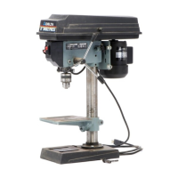
Assemble the drill press column to the base using hex head cap screws.
Attach the drill press table to the column as shown in the figure.
Thread the clamp handle into the rear of the table bracket to secure the table.
Place the drill press head onto the column and tighten the head locking screws.
Thread the pinion shaft handles into the three holes in the pinion shaft.
Clean rust protectant from spindle taper and chuck, then push chuck onto spindle.
Open chuck jaws, tap chuck onto spindle using a mallet or wood block for proper seating.
Ensure the belt is properly tensioned, not too tight or loose, for optimal performance and longevity.
Use properly sized, heavy-gauge, 3-wire extension cords with grounding plugs for safe operation.
Lift the belt and pulley guard to access the pulleys and belt.
Loosen the tension lock knob and pivot the motor to release belt tension.
While holding the motor, position the belt on the desired pulley steps for speed change.
Pivot motor to tension belt properly; it should flex about 1 inch with light pressure.
Remove the switch toggle to prevent unauthorized use of the drill press when not in use.
Loosen the table clamp handle to raise or lower the table to the desired position.
Remove the alignment pin to tilt the table right or left for angled drilling.
Replace alignment pin to automatically set table surface at 90 degrees to the spindle after tilting.
Use the tilt scale and witness line to indicate and set the desired degree of table tilt.
Loosen the two nuts on the spring housing approximately 1/4 inch to begin adjustment.
Rotate the spring housing to engage notches, adjusting tension clockwise/counterclockwise.
Thread stop nuts on the rod to set the desired depth and contact the depth stop.
Drill a test hole to verify depth adjustment and re-adjust if necessary.
Position workpiece against column or clamp it to the table to prevent rotation during drilling.
| Brand | Delta |
|---|---|
| Model | 11-950 |
| Category | Power Tool |
| Language | English |