EasyManua.ls Logo

Delta 37-070 - User Manual

Delta 37-070
21 pages
Print Icon
To Next Page IconTo Next Page
Loading...
INSTRUCTION MANUAL
6" Variable Speed
Bench Jointer
(Model 37-070)
PART NO. 901609 (013)
Copyright © 2001 Delta Machinery
ESPAÑOL: PÁGINA 21
To learn more about DELTA MACHINERY
visit our website at: www.deltamachinery.com.
For Parts, Service, Warranty or other Assistance,
please call
1-800-223-7278 (In Canada call 1-800-463-3582).
Question and Answer IconNeed help?

Do you have a question about the Delta 37-070 and is the answer not in the manual?

Summary

Delta 6 Variable Speed Bench Jointer Manual

General Safety Rules

Key Safety Precautions

Essential safety rules for safe operation of the jointer.

Additional Jointer Safety Rules

Safe Jointer Operating Procedures

Specific safety guidelines for performing jointer operations.

Power and Grounding

Tool Grounding Instructions

Critical safety procedures for proper tool grounding.

Extension Cords and Initial Setup

Understanding Jointer Operations

Assembly Instructions

Assembling the Fence System

Steps to assemble the fence mounting and sliding brackets.

Assembling Cutterhead Guards and Locks

Operating Controls and Safety Measures

Switch Operation and Locking

How to start, stop, and lock the power switch for safety.

Adjusting Machine Settings

Variable Speed Control Settings

Adjusting cutterhead speed and using the speed control chart.

Jointer Knife Adjustment

Knife Adjustment Procedure

Steps for adjusting or replacing jointer knives for proper performance.

Basic Jointer Operation

Advanced Jointer Operations

Maintenance Procedures

Overview

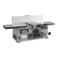
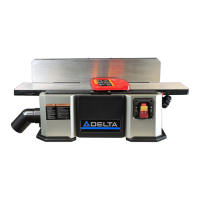
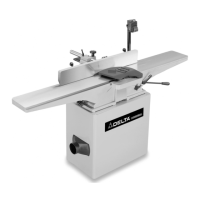
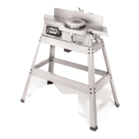
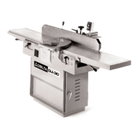
This document is the instruction manual for the Delta Model 37-070 6" Variable Speed Bench Jointer.

Function Description

The Delta Model 37-070 is a woodworking tool designed for jointing and planing operations. Jointing involves squaring an edge of a workpiece by positioning the narrow edge on the infeed table and the major flat surface against the fence, then moving it across the cutterhead to the outfeed table. Planing (or surfacing) is similar, but the major flat surface of the workpiece is placed on the infeed table with the narrow edge against the fence. The tool is used to create straight, flat surfaces on wood, remove warps, and prepare edges for joining.

Important Technical Specifications

  • Model: 37-070
  • Type: 6" Variable Speed Bench Jointer
  • Cutting Capacity: 6" (152mm) width and 1/8" (3mm) depth
  • Motor: 10 amp, 120 volt
  • Variable Speed Range: 6000 to 11,000 RPM (Revolutions Per Minute)
  • Cutting Speed Range: 12,000 to 22,000 CPM (Cuts Per Minute)
  • Cutterhead: Two-knife cutterhead
  • Power Connection: Requires a separate electrical circuit, not less than #12 wire, protected with a 20 Amp time lag fuse. For extension cords, use only 3-wire grounding type plugs and 3-hole receptacles.
  • Power Requirements: 120 volt, 60 HZ alternating current.
  • No-load Speed: 6000 - 11000 RPM.

Usage Features

  • Variable Speed Control: The jointer features a variable speed control knob (A, Fig. 23) with speed indicators (1-5) to adjust cutterhead speeds between 6000 and 11,000 RPM. A speed control chart (C, Fig. 23) provides recommended settings for jointing plastics, softwoods, and hardwoods from 1-1/2" to 6" wide.
  • Depth of Cut Adjustment: The jointer can be set to cut any depth from a very thin shaving up to 1/8" deep. It includes a dual English/Metric scale (A, Fig. 24) and pointer (B) for indicating the depth of cut. Adjustment is made by loosening a lock knob (C) and turning an adjusting knob (D) to raise or lower the infeed table.
  • Fence Adjustments: The fence can be moved across the table and tilted up to 45 degrees to the right.
    • Moving Across Table: Loosen lock lever (A, Fig. 25), slide the fence to the desired position, and tighten the lever. The lock lever is spring-loaded and can be repositioned.
    • Tilting Fence: Loosen lever (B, Fig. 25), tilt the fence to the desired angle, and tighten the lever. This lever is also spring-loaded and repositionable.
    • Positive Stops: The fence has adjustable positive stops at 90 and 45 degrees to the right for rapid positioning. These stops are adjusted using set screws (D, F, Fig. 27, 29) after checking with a square (C, Fig. 26, 28).
  • Safety Features:
    • Cutterhead Guard: A cutterhead guard (12, Fig. 4) is included and must be in place during operation.
    • Cutterhead Lock: A cutterhead lock (13, Fig. 4) is provided for safety, to be engaged only when setting knives (A, Fig. 15) and disengaged at all other times (A, Fig. 16).
    • Push Blocks: Two push blocks (11, Fig. 4) are supplied and should be used whenever possible, especially for material less than 3 inches in height or thinner than 3 inches, to minimize hand danger (A, Fig. 37).
    • Switch Lock: The on/off switch (A, Fig. 21) can be locked in the "OFF" position by removing the switch toggle (B, Fig. 22) to prevent unauthorized use.
  • Workpiece Dimensions:
    • Jointing: Do not perform jointing operations on material shorter than 10 inches, narrower than 3/4 inch, or less than 1/2 inch thick (Fig. 39A).
    • Planing: Do not perform planing operations on material shorter than 10 inches, narrower than 3/4 inch, wider than 6 inches, or less than 1/2 inch thick (Fig. 40A).
    • Depth of Cut Limit: Never make jointing or planing cuts deeper than 1/8 inch. For cuts wider than 1-1/2 inches, adjust depth to 1/16 inch or less to avoid overloading and kick-back.
  • Feeding Direction: Work must be fed into the blade or cutter against the direction of rotation. Feeding with the grain is crucial for a smooth surface; feeding against the grain can cause chipped and splintered edges (Fig. 41, 42).
  • Workpiece Support: Always hold the workpiece firmly against the tables and fence and support it adequately throughout the operation. Do not back the workpiece toward the infeed table.
  • Dust Chute: A chip and dust chute (A, Fig. 35) is provided on the outfeed end of the jointer base for efficient chip removal.

Maintenance Features

  • Knife Adjustment: When knives need adjustment due to replacement or wear:
    1. Disconnect power and remove the cutterhead guard.
    2. Rotate the cutterhead and loosen four screws (A, Fig. 30) by about half a turn.
    3. Engage the cutterhead lock (B, Fig. 31) to position knives for adjustment.
    4. Place a straight edge (C, Fig. 31) on the outfeed table, extending over the knife. Use a wrench (D) to turn screw (E) until the knife just touches the straight edge. Adjust the knife at the far end using screw (F).
    5. Tighten the four screws (A, Fig. 30) after adjustment.
    6. Disengage the cutterhead lock and replace the cutterhead guard.
    • Knife Setting Impact: Knives set too low will result in a curved finished surface (Fig. 32). Knives set too high will gouge the work at the end of the cut (Fig. 33). A final check involves running a piece of wood slowly over the knives to ensure it rests firmly on both tables with no open spaces (Fig. 34).
  • Belt Replacement:
    1. Disconnect power.
    2. Remove screw (A, Fig. 43) and belt guard (B).
    3. Loosen three screws (C, Fig. 44) to release belt tension and remove belt (D).
    4. Assemble the new belt to the cutterhead and motor pulleys.
    5. Press down on the motor pulley (E, Fig. 44) to tension the belt and tighten the three screws (C).
    6. Replace the belt guard (B, Fig. 44).
  • General Maintenance: Keep tools sharp and clean for best performance. Follow instructions for lubricating and changing accessories. Disconnect tools before servicing or changing accessories.
  • Cleaning: Remove protective coating from unpainted surfaces with a soft cloth moistened with kerosene (avoid acetone, gasoline, or lacquer thinner). Cover unpainted surfaces with a good quality household floor paste wax after cleaning.
  • Cord Storage: A cord storage bracket (A, Fig. 36) is provided on the jointer base for storing the power cord when the machine is not in use.

Delta 37-070 Specifications

General IconGeneral
BrandDelta
Model37-070
CategoryPower Tool
LanguageEnglish

Related product manuals