Do you have a question about the Delta 37-380 and is the answer not in the manual?
Comprehensive safety rules and important instructions to prevent injury and ensure safe operation of the equipment.
Ensuring proper electrical grounding for user safety and preventing electric shock hazards during operation.
Instructions for securely mounting the jointer unit onto its stand, including motor and switch wiring.
Instructions on how to safely start and stop the jointer using the on/off switch.
How to raise or lower the infeed table using the locking handles and adjustment lever.
Steps for ensuring the outfeed table is level with the knives for accurate jointing operations.
Guide on correctly installing, removing, and setting jointer knives for optimal cutting performance.
Step-by-step guide for safely removing, replacing, and resetting jointer knives.
Adjusting knife height relative to the cutterhead and rear table using feeler gauges and straight edges.
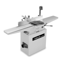
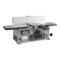
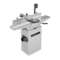
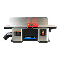
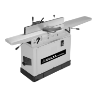
This document is a user manual for the Delta 8" Professional Jointer, Model 37-380. It provides comprehensive instructions for assembly, operation, and maintenance of the woodworking machine, emphasizing safety throughout.
The jointer is designed for woodworking operations, specifically for creating flat and square surfaces on lumber. Its primary function is to straighten and smooth the edges and faces of wood pieces, preparing them for further processing or assembly. The machine features an infeed and outfeed table, a cutterhead with three knives, a fence, and a cutterhead guard. It is powered by a 1-1/2 hp, 120/240 volt induction motor.
The manual begins with crucial safety guidelines, defining warning symbols (DANGER, WARNING, CAUTION) and their implications for personal safety and equipment protection. It highlights the importance of reading and understanding all instructions before use to prevent electric shock, fire, or injury. General safety rules include wearing certified safety equipment (eye protection, hearing protection, dust mask), dressing properly (no loose clothing or jewelry), and operating the machine in a safe, well-lit environment. Users are advised to maintain tools in peak condition, check for damaged parts, keep the work area clean, and keep children and visitors away. Preventing unintentional starting by ensuring the switch is in the "OFF" position before plugging in and using guards are also emphasized. The manual instructs users to remove adjusting keys and wrenches before starting, use the correct machine for the job, and utilize recommended accessories. Proper extension cord usage is detailed with a chart for appropriate gauge selection based on cord length and ampere rating. Workpieces should be secured with clamps or a vise, and fed against the direction of blade rotation. Forcing the workpiece, overreaching, or standing on the machine are prohibited. The machine should never be left running unattended and must be disconnected from the power source before adjustments or repairs. Childproofing the workshop with padlocks or master switches is also recommended.
Specific additional safety rules for jointers are provided. Users must not operate the machine until it is fully assembled and installed. Seeking advice from a supervisor or instructor if unfamiliar with operation is encouraged. All wiring codes and electrical connections must be followed. Knives should be kept sharp and free from rust and pitch. The infeed and outfeed tables must be tightened before starting. Blades must be properly secured in the cutterhead. The machine should never be turned on with objects on the table or with the workpiece contacting the cutterhead. Awkward operations and hand positions should be avoided, keeping arms, hands, and fingers away from the cutterhead. Cuts deeper than 1/8" (3.2mm) are not recommended to prevent kickback. Workpieces shorter than 10" (254mm), narrower than 3/4" (19.0MM), or less than 1/2" (12.7mm) thick should not be jointed or planed. Hold-down/push blocks are essential for small workpieces. The workpiece must be held firmly against the table and fence. "Free-hand" operations are prohibited, and abnormal or little-used operations require careful study and appropriate jigs. Feeding the workpiece into the outfeed end is dangerous. Warped wood, knots, or foreign objects should not be fed into the machine. Maintaining the proper relationship between infeed and outfeed table surfaces and the cutterhead knife path is critical. Long or wide workpieces require proper support. Layout, assembly, or setup work should not be performed while the machine is running. The machine must be turned off, disconnected, and cleaned before leaving. Locking the switch in the "OFF" position prevents unauthorized use.
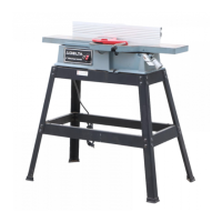
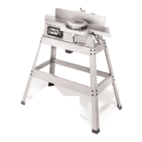
The manual details the assembly process, starting with attaching the jointer to its stand. This involves removing the back panel of the stand, aligning the motor mounting plate with the motor mounting brackets, and securing the motor. The stand is then turned over, and the jointer base is aligned with the stand, securing it with screws, washers, and nuts. Assembling the infeed table adjustment handle involves threading a hex nut onto the handle and then threading the handle into a block under the infeed table, tightening the hex nut against the block.
Motor pulley assembly requires attaching the motor pulley to the motor shaft, ensuring the key is inserted, and tightening the set screw. For belt and pulley alignment, the belt is placed in the grooves of both pulleys. A straight edge is used to ensure proper alignment, and adjustments are made by moving the motor pulley or shifting the motor. Belt tension is adjusted by raising or lowering the motor until approximately 1" of deflection is achieved with light finger pressure. The cutterhead pulley guard/carriage bracket is positioned using alignment pins and secured with screws, lockwashers, and flat washers. The fence carriage assembly is then fastened to the cutterhead pulley guard/carriage mounting bracket, aligning holes and securing with hardware. Finally, the fence is attached to the fence carriage assembly in a similar manner.
The cutterhead guard assembly involves inserting the guard post through a hole in the infeed table, ensuring the spring in the knob assembly provides tension to return the guard over the cutterhead. The set screw is then threaded back into the post to keep the guard in position during operation.
Switch and mounting bracket assembly involves aligning the switch mounting bracket with holes in the infeed table and securing it with screws, lockwashers, and flat washers. The switch is then aligned with the mounting bracket and fastened with a hex head screw, flat washer, lockwasher, and hex nut.
Dust chute assembly involves fastening the supplied dust collector connector to the jointer stand with sheet metal screws. A standard 4" dust collection hose can then be attached.
Operating controls and adjustments are clearly explained. To start the jointer, the switch shield is lifted, and the switch is moved to the "ON" position. To turn it off, the switch shield is pushed down. For safety, the switch can be locked in the "OFF" position by inserting a padlock shank through holes in the switch plate.
Infeed table adjustments involve loosening table locking handles at the rear and front of the infeed table, then raising or lowering the adjustment lever. A depth stop automatically limits the depth of cut to 1/8". To move the table past this point, the depth stop must be raised while lowering the infeed table. Locking handles must be tight before operation. The depth-of-cut is indicated on a scale, with a maximum of 1/2" achievable in 1/8" increments. Positive stops are provided to limit infeed table height and depth. These are adjusted by loosening locknuts and turning adjusting screws.
Outfeed table adjustments are crucial for accurate jointing. The outfeed table must be exactly level with the knives at their highest point of revolution. This is achieved by loosening a lockscrew and turning a hand knob. Once level, the lockscrew is tightened.
Knife adjustments are detailed for accurate work, ensuring knives are level with the outfeed table. This involves loosening the infeed table lock lever, lowering the infeed table, and removing the cutterhead guard. A steel straight edge is placed on the outfeed table, extending over the cutterhead, and the cutterhead is rotated by hand to check if the knives just touch the straight edge. If a knife is high or low, the locking bar screws are loosened, and the knife raising screws are turned to adjust height. Extreme care is advised when handling sharp knives. After adjustment, the locking screws are tightened. The process is repeated for all knives, and the cutterhead guard is replaced. The manual illustrates the results of knives set too low (curved surface) or too high (gouged, curved, or bowed end). A final check involves slowly running a piece of wood over the knives to ensure it rests firmly on both tables with no open spaces.
Adjusting table gibs is covered to take up any play that may develop between the base and tables due to wear. For the infeed table gib, locking knobs and locknuts are loosened, and adjustment screws are tightened or loosened. The lower screw is adjusted first, gently raising the outboard edge of the table to offset any "droop or sag." For the outfeed table gib, the locking lever and locknuts are loosened, and adjustment screws are adjusted similarly, gently raising the outboard edge. It's important not to leave adjustment screws too loose, as some effort should be required to raise and lower the tables.
Fence operation allows the fence to be moved across the table and tilted 45 degrees right or left. To move the fence, a lock handle is loosened, and a knob is turned. To tilt the fence, a lock handle is loosened, and a tilting handle is used to rotate the fence to the desired angle. For small bevels, tilting the fence in or out makes little difference, but for angles approaching 45 degrees, tilting the fence toward the table (creating a V-shape) is recommended for secure workpiece holding.
Adjusting fence positive stops allows rapid tilting to 90 and 45-degree angles. To check and adjust, the fence is positioned at 90 degrees, ensuring the flip stop is lowered and the adjustment screw contacts it. A square is used to verify the 90-degree angle. If adjustment is needed, the locking handle and locknut are loosened, and the adjustment screw is rotated. The process is similar for 45-degree outward and inward tilts.
Removing, replacing, and resetting knives is a critical maintenance task. The fence is moved to the rear, and the cutterhead guard is removed. Extreme caution is advised due to sharp knives. Locking screws in each knife slot are slightly loosened, then further loosened to remove the knife and knife locking bar. The knife adjustment blocks are lowered by turning screws counterclockwise. Before replacing knives, the locking bars must be clean. Knives and locking bars are replaced into each slot, pushing the knife down as far as possible and snugging up the screws. Knives must be securely fastened before turning on power.
Knife adjustment for correct extension is described: knives should extend 0.060" from the cutterhead diameter. The cutterhead is rotated until the round portion is on top. A 0.060" feeler gauge and a straight edge are used on the rear table to adjust its height until it is 0.060" above the cuttinghead diameter. The rear table is then locked, and the feeler gauge removed. The infeed table is lowered, and a straight edge is placed on the outfeed table, extending over the cutterhead. The cutterhead is rotated by hand until the knife is at its highest point at each end. The wrench is used to raise the knife by turning the raising screw clockwise until the knife just touches the straight edge at both ends and the center of the cutterhead. Once adjusted, the four locking screws are tightened counterclockwise. This process is repeated for all knives.
The manual also covers operational techniques such as jointing an edge, surfacing, beveling, taper cuts, and cutting a rabbet. It emphasizes using push blocks for surfacing short or thin work and avoiding feeding against the grain to prevent chipped edges.
For long-term maintenance, the manual describes whetting knives using a fine carborundum stone, covering it partly with paper to avoid marking the table. The stone is laid on the infeed table, the table is lowered, and the cutterhead is turned forward until the stone lies flat on the knife's bevel. The beveled edge is whetted by stroking the stone back and forth across the table, ensuring equal whetting on each knife.
Finally, the manual includes a pattern for constructing a push stick, an essential safety accessory for handling narrow or short stock.
| Type | Jointer |
|---|---|
| Motor Power | 1.5 HP |
| Blade Length | 6 inches |
| Max Depth of Cut | 1/8 inch |
| Table Length | 37 inches |
| Table Width | 6 inches |
| Fence Tilt | 45 degrees |
| Dust Port Size | 2.5 inches |