10
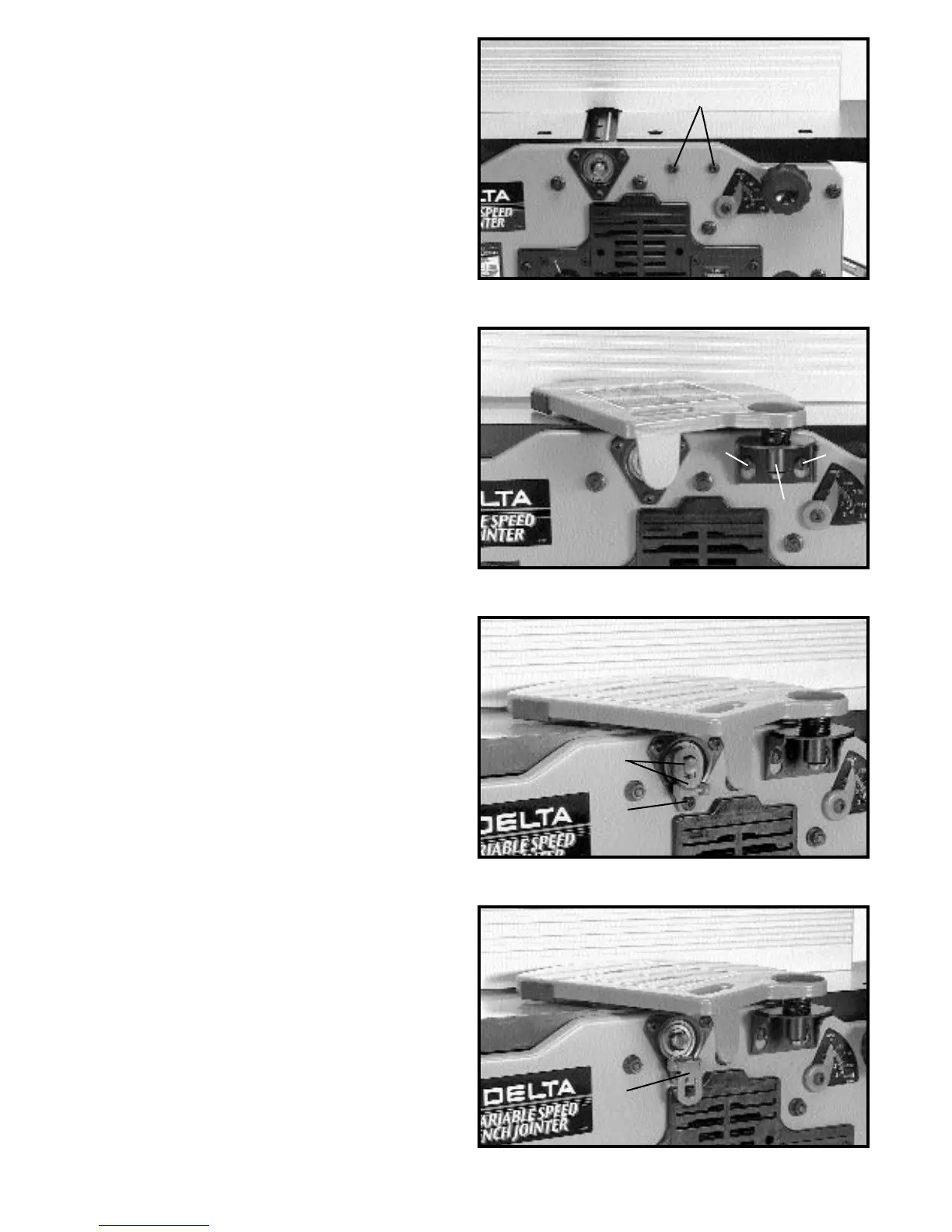
Fig. 13
Fig. 14
Fig. 15
Fig. 16
ASSEMBLING
CUTTERHEAD GUARD
1. Thread the two 7/16" long socket button head
screws (A) Fig. 13, into the two threaded holes in front
side of jointer base. DO NOT COMPLETELY TIGHTEN
SCREWS (A) AT THIS TIME.
2. Assemble guard mounting bracket (B) Fig. 14, to the
two screws (A) as shown, and tighten the two screws (A).
ASSEMBLING
CUTTERHEAD LOCK
1. Assemble cutterhead lock (A) Fig. 15, to the front
side of the jointer base, using the 7/16" long socket
button head screw (B). NOTE: THE CUTTERHEAD
LOCK (A) IS TO BE ENGAGED WITH THE
CUTTERHEAD SHAFT AS SHOWN IN FIG. 15. ONLY
WHEN SETTING KNIVES. ALL OTHER TIMES THE
CUTTERHEAD LOCK (A) SHOULD BE DISENGAGED
FROM THE CUTTERHEAD, AS SHOWN IN FIG. 16.
A
B
A
A
A
B
A