9
9
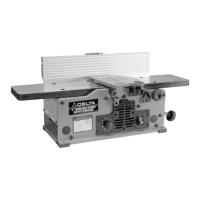
Fig. 9
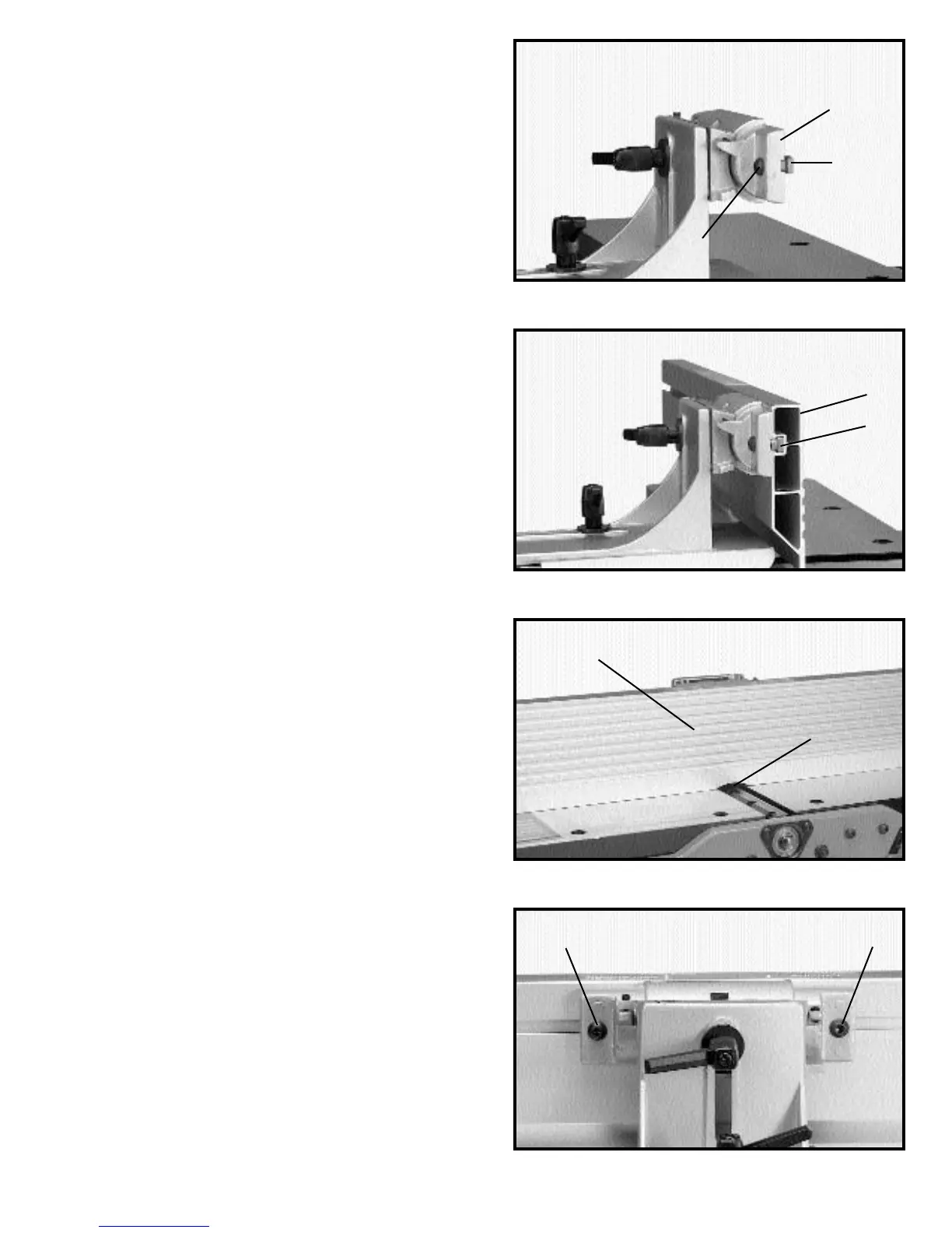
Fig. 10
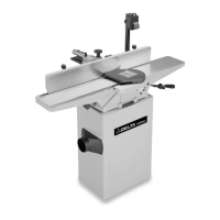
Fig. 11
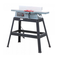
Fig. 12
6. Tighten two screws (G) Fig. 12.
5. Position fence (L) Fig. 11, so that rounded section
(M) on bottom of fence is over cutterhead opening as
shown.
4. Slide groove of fence (L) Fig. 10, over T-nuts (J) as
shown.
3. Assemble 5/8" long socket button head screw (G)
Fig. 9, to fence tilting bracket (H) and thread T-nut (J)
onto threaded end of screw (G) as shown. DO NOT
COMPLETELY TIGHTEN SCREW (G) AT THIS TIME.
Assemble screw and T-nut to opposite end of tilting
bracket in the same manner.
H
J
G
L
J
M
L
G
G