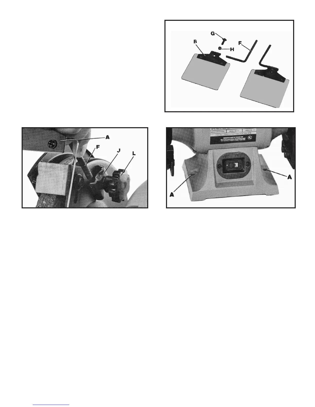
Fig. 5
Fig. 6
Fig. 7
2. Insert the short end of mounting rod (F) Fig. 5, into
hole of frame (B) and fasten in place with 3/4 inch-long
square necked round head screw (G) and nut (H).
3. Assemble long end of eye shield mounting rod (F)
Fig. 6, to the side of each wheel guard using bracket (J),
lockwasher and locking knob (L). The eye shield (A) is fully
adjustable so it can be put in any position by moving the
shield (A) or loosening locking knob (L) and repositioning
rod (F).
CONNECTING GRINDER TO POWER SOURCE
POWER CONNECTIONS
A separate electrical circuit should be used for your tools. This circuit should not be less than #12 wire and should be
protected with a 20 Amp fuse. Have a certified electrician replace or repair a worn cord immediately. Before connecting
the motor to a power line, make sure the switch is in the ‘“OFF” position and be sure that the electric current is of the
same characteristics as stamped on the motor nameplate. Running on low voltage will damage the motor.
WARNING: DO NOT EXPOSE THE TOOL TO RAIN OR OPERATE THE TOOL IN DAMP LOCA-
TIONS.
MOTOR SPECIFICATIONS
Your grinder is wired for 110-120 volt, 60 HZ alternating current. Before connecting the grinder to the power source, make
sure the switch is in the “OFF” position.

 Loading...