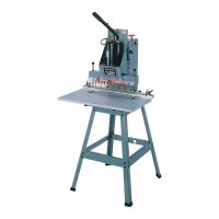
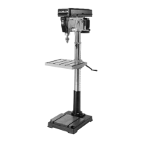
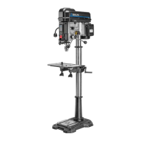
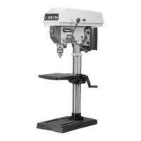
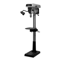
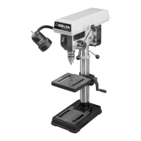
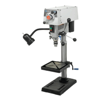
This document describes the 13-Spindle Line Boring Machine (Model 32-325) and the 13-Spindle Pneumatic Line Boring Machine (Model 32-326), both designed for woodworking applications. These machines are primarily used for boring multiple holes in a straight line, a common task in cabinet making and furniture construction. The pneumatic model offers enhanced automation for increased efficiency.
Function Description
The core function of both models is line boring, which involves drilling a series of holes at precise, consistent intervals along a workpiece. This is achieved using a multi-spindle boring head equipped with thirteen bits. The machines are designed to bore holes with a 32mm center distance between each hole, a standard measurement in many woodworking systems.
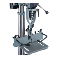
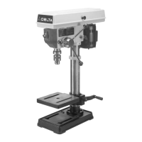
The Model 32-325 is a manual line boring machine. The operator controls the lowering and raising of the boring head using a handle. This handle can be adjusted for multi-position use, allowing for extra leverage when boring holes, and can be pushed in to move it out of the way when not in use. The depth of the boring bits above the table surface is controlled by a stop bracket and a stop screw. The operator loosens a lock knob, moves the stop bracket to align with the desired mark on a scale, and then tightens the lock knob. The stop screw prevents the boring head from lowering beyond the set depth. There is also a stop on the left side of the machine to ensure even depth across the line of holes.
The Model 32-326 is a pneumatic line boring machine, which automates the boring process. It incorporates an air cylinder for head lowering and raising, and air clamps to secure the workpiece. To operate, the motor cord is plugged into the control box, and the motor on-off switch is turned to "ON." The machine starts when the operator presses and holds the start button. This action activates the air clamps, which firmly hold the workpiece against the table. Simultaneously, the motor starts, and the boring head lowers to its pre-set depth. Upon completion of the boring operation, the boring head automatically raises, and the motor shuts off. Releasing the start button at any point during the cycle will cause the motor to shut off and the boring head to return to the up position. A limit switch controls the downward travel of the boring head, stopping it at the pre-set depth and initiating its return to the up position. A reset button is provided to raise the air clamp plungers, allowing for workpiece repositioning and restarting the machine.
Both machines feature a large 16"x29 3/4" table, providing ample workspace for boring extra-large boards. A fence system is used to position the workpiece accurately. The fence can be moved in or out to bore holes up to four inches from the edge of the workpiece. Indexing pins, in conjunction with a scale, assist in precise fence positioning. Fence stops are provided to help position the workpiece for repetitive boring operations, allowing for multiple series of holes to be bored at different distances from the workpiece edge.
Usage Features
- Assembly and Setup: Both machines require assembly of the stand (if purchased as an accessory), the table, and the fence. The stand assembly involves securing legs and braces with carriage bolts, flat washers, and hex nuts. The machine is then fastened to the stand using hex head screws, flat washers, lockwashers, and hex nuts. If not using the accessory stand, the machine must be fastened to a suitable supporting surface.
- Table and Fence Assembly: Table slides are clipped to table brackets, and the table is centered on the machine frame. The table brackets are then fastened to the table and machine frame using flat head screws and lock nuts. Carriage bolts, flat washers, and lock knobs secure the table in place. Spacers, lockwashers, and hex head screws are used to attach the fence to the table bracket. It is important not to fully tighten hardware during initial assembly steps to allow for adjustments.
- Aligning Fence Parallel to Boring Head: A gage is used to align the fence. Indexing pins are lowered to engage holes in the gage. Table lock knobs are loosened, and the table is moved until the front end of the fence is approximately 1/32" away from the gage. The fence is then adjusted until its front surface contacts the gage, and the right fence stop contacts the gage.
- Adjusting Table Parallel to Fence: After removing the gage, the index pins should point to the 2-1/4" mark on both scales. If adjustment is needed, four screws fastening the table to the machine frame are loosened, and the table is adjusted until the index pins align with the 2-1/4" mark.
- Boring Bit Assembly and Alignment: The machines accept bits with 10mm shanks. Thirteen set screws are threaded into each spindle. Boring bits are inserted into the spindles as far as possible, and the set screws are tightened against the flat on the bit. For the 13-spindle machine, seven right-hand rotation bits and six left-hand rotation bits are required, with a right-hand bit in the center spindle and alternating thereafter. Bit alignment is crucial for consistent hole depth. A flat piece of wood is placed on the table, and the boring head is lowered until any one bit contacts the wood. Bits that do not contact the wood are removed, their set screws loosened by the amount they did not contact the wood, and then reassembled and tightened. This process is repeated until all bits contact the wood surface simultaneously.
- Clear Plastic Guard Assembly: A clear plastic guard is assembled to the front of the boring head, engaging slots with spacers and screws. It may be necessary to bend the guard slightly outward at the center during assembly.
- Wrench Storage: A dedicated hole with a rubber grommet is provided on top of the machine for storing the supplied wrench.
- Air Connections (Pneumatic Model): A 1/4" female pipe thread on the air filter connects the air line to the machine. An air supply of 90 psi is recommended, not exceeding 125 psi.
- Adjusting Air Pressure (Pneumatic Model): An air pressure gage and regulator are used to set the operating air pressure. The regulator is pulled out, turned until the desired pressure (90 psi recommended) is indicated on the gage, and then pushed back into the locked position.
- Moving Fence and Table: Table lock knobs are loosened to move the table and fence in or out, allowing for holes to be bored at different distances from the workpiece edge. The index pin and scale are used for precise positioning.
- Fence Stops: Two spring-loaded fence stops (right and left) are provided, which can be moved along the fence scale. These stops assist in positioning the workpiece for repetitive boring operations. When a stop is not in use, it can be pushed back to allow the workpiece to sit flush against the fence.
- Line Boring Operation: For multiple holes beyond the 13-spindle capacity, the workpiece is slid along the fence, and an indexing pin is pushed down into the last previously bored hole to align the workpiece for the next series of holes.
Maintenance Features
- Cleaning: Upon unpacking, protective coating should be removed from unpainted surfaces using a soft cloth moistened with kerosene. Acetone, gasoline, or lacquer thinner should not be used. After cleaning, unpainted surfaces should be covered with a good quality household floor paste wax.
- General Safety Rules: Regular maintenance includes keeping guards in place and in working order, ensuring drill bits are sharp and free of rust and pitch, and checking drill bits for damage.
- Tool Condition: Tools should be kept sharp and clean for best and safest performance. Lubrication and accessory changes should follow instructions.
- Disconnection for Service: The machine must be disconnected from the power source before servicing, changing accessories (blades, bits, cutters), or making repairs.
- Damaged Parts: Before further use, any damaged guard or part should be carefully checked to ensure proper operation. Damaged parts should be properly repaired or replaced.
- Cord Maintenance: Damaged or worn power cords should be repaired or replaced immediately.
- Air Filter (Pneumatic Model): The air filter should be correctly assembled, ensuring the air flow directional arrow is followed.
- Locking Switch: When the machine is not in use, the switch should be locked in the "OFF" position using a padlock to prevent unauthorized use.