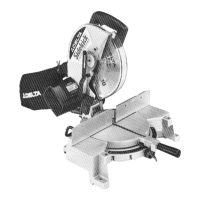
The document describes the Delta 10" Compound Power Miter Saw, Model 36-075, a woodworking tool designed for precise angle cuts in wood.
Function Description:
The Delta 36-075 is a compound miter saw primarily used for cutting wood. Its main function is to make accurate crosscuts, miter cuts, and bevel cuts. A key feature is its "compound" capability, meaning it can simultaneously make both miter and bevel cuts, allowing for complex angle combinations, such as those required for crown molding. The saw is designed for stationary use, requiring firm mounting to a workbench or supporting surface for safe and effective operation.
Important Technical Specifications:
- Blade Diameter: 10 inches. The manual emphasizes using only 10" diameter saw blades rated for 6000 RPM or higher and having 5/8" diameter arbor holes.
- Blade Type: Specifically designed for cross-cutting saw blades. For carbide-tipped blades, a negative hook angle is recommended, and blades with deep gullets should be avoided as they can deflect and contact the guard.
- Motor: Wired for 110-120 volt, 60 HZ alternating current.
- No-Load Speed: 5200 RPM.
- Electrical Circuit: Requires a separate electrical circuit, not less than #12 wire, protected with a 20 Amp time lag fuse.
- Grounding: The tool is grounded and requires a 3-wire extension cord with a 3-prong grounding type plug and 3-pole receptacles.
- Cutting Capacity:
- Crosscut: Up to 5-3/4" x 2-3/8" at a straight 90-degree cut.
- Miter (45 degrees left and right): 4-1/8" x 2-3/8".
- Bevel (45 degrees left): 5-7/8" x 1-9/16".
- Compound (45 x 45 degrees): 4-1/8" x 1-9/16".
- Miter Angles: Positive stops at 0, 22.5, and 45 degrees both left and right.
- Bevel Angles: Adjustable bevel stops at 0 and 45 degrees. The cutting head can tilt from a straight 90-degree cut to a 45-degree left bevel angle.
- Blade Brake: Equipped with an automatic electric blade brake that stops the blade in seconds upon releasing the switch trigger.
Usage Features:
- Safety First: The manual strongly emphasizes reading the instruction manual, wearing eye protection, keeping guards in place, and disconnecting power before servicing or changing accessories. It also highlights a "Table Hazard Area" (the area inside two red lines on the table) where hands should never be placed during operation.
- Table Lock Handle: Used to secure the table at desired miter angles. It can be loosened to rotate the table and depressed to release positive stops.
- Cuttinghead Lock Knob: Used to lock the cuttinghead in the down position for transport or to release it for operation.
- Miter Scale and Pointer: A pointer indicates the actual angle of cut, with each line on the scale representing 1 degree. An adjustment screw allows for pointer calibration.
- Bevel Lock Handle: Used to tilt and secure the cutting arm for bevel cuts.
- Positive Stops: Both miter and bevel settings have positive stops for rapid positioning at common angles (0, 22.5, 45 degrees for miter; 0, 45 degrees for bevel).
- Crown Molding Indicators: Triangle indicators are provided on both the miter scale (at 31-5/8 degrees) and bevel scale (at 33-7/8 degrees) for specific crown molding cuts.
- Rear Support/Carrying Handle: A pull-out bar at the rear prevents tipping when the cuttinghead is up and doubles as a carrying handle for transport.
- Dust Bag: Collects sawdust during operation, attaching to the dust spout.
- Work Clamp: An accessory (Model 36-221) is shown for firmly clamping workpieces against the fence, which is crucial for safety and accuracy, especially when hands would otherwise be in the hazard zone.
- Auxiliary Wood Fence: Can be mounted to the saw's fence for specific operations, particularly with the blade in the 0-degree bevel position. It must be removed for bevel cutting.
- Cutting Bowed Material: Specific instructions are provided on how to position bowed material correctly to prevent pinching the blade.
- Cutting Aluminum: The saw can cut aluminum extrusions using a stick wax lubricant (applied before running the machine) and proper material positioning to cut through the smallest cross-section.
Maintenance Features:
- Blade Changing: Detailed instructions are provided for safely changing the saw blade, including disconnecting power, removing guards, using hex and arbor wrenches, and ensuring the new blade's teeth point down at the front.
- Brush Inspection and Replacement: Instructions for inspecting and replacing motor brushes are included, with a recommendation to check them after the first 50 hours of use and then every 10 hours until replacement is needed.
- Adjusting Blade Parallel to Table Slot: Steps to ensure the saw blade is parallel to the left edge of the table opening by loosening and tightening screws on the cutting arm.
- Adjusting Fence 90 Degrees to Blade: Procedure for adjusting the fence to be 90 degrees to the blade using a square, after ensuring the blade is parallel to the table slot.
- Adjusting Downward Travel of Saw Blade: Instructions to limit the blade's downward travel to prevent contact with metal surfaces, involving loosening a locknut and turning an adjusting screw.
- Adjusting 90 and 45 Degree Bevel Stops: Procedures for calibrating the positive bevel stops at 90 and 45 degrees to the table using a square, involving loosening locknuts and turning adjustment screws.
- Adjusting Cuttinghead Return Spring Tension: Steps to re-adjust the spring tension if the cuttinghead does not return to the up position properly after a cut.
- General Maintenance: Keep tools sharp and clean, follow lubrication instructions, and check for damaged parts. The manual advises cleaning plastic parts with a soft damp cloth, avoiding solvents.