EasyManua.ls Logo

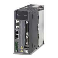
Delta ASD-A2-0421 Series - User Manual

Delta ASD-A2-0421 Series
721 pages
Print Icon
To Next Page IconTo Next Page
Loading...
V5.1
DELTA_IA-ASDA_A2_UM_EN_20170209

Table of Contents

Other manuals for Delta ASD-A2-0421 Series

Questions and Answers

  • A
    Ana RichardsAug 31, 2025
    What causes overspeed in Delta ASD-A2-0421 Servo Drives?
    • M
      Matthew HuffAug 31, 2025
      Overspeed in Delta Servo Drives can be triggered by: * Unstable speed input command (too much fluctuation). If this is the case, ensure that input command frequency is stable (not fluctuate too much) and activate filter function. * Defective over-speed parameter setting. If this is the case, correctly set over-speed parameter setting (P2-34).
  • T
    Tyler LittleAug 25, 2025
    What causes undervoltage in Delta ASD-A2-0421 Servo Drives and how to fix it?
    • T
      Terry VaughnAug 25, 2025
      Undervoltage in Delta Servo Drives can be caused by: * The main circuit voltage being below its minimum specified value. If this is the case, reconfirm voltage wiring. * No input voltage at the main circuit. If this is the case, reconfirm the power switch. * Incorrect power input. If this is the case, use the correct power supply, a stabilizing power supply, or a series transformer.
  • J
    Jeffrey ReedSep 23, 2025
    How to fix An error occurs when loading CANopen data in Delta Servo Drives?
    • D
      David WilliamsSep 23, 2025
      To fix an error occurs when loading CANopen data in Delta Servo Drives, when an error occurs when loading data via EEPROM, use DI.ARST, CANopen 0x1011 Restore default parameter.
  • A
    antoniosmithSep 5, 2025
    What to do if CANopen PDO object does not support PDO on Delta Servo Drives?
    • D
      daryl22Sep 5, 2025
      If the specified object in the message does not support PDO, NMT Maser send “Reset node“ command to its slave or reset the fault by sending the control word (0x6040) through CAN communication (the value of CANopen object 0x6040 should be reset).
  • D
    Donna JohnsonSep 9, 2025
    What to do if Delta Servo Drives show abnormal pulse command?
    • T
      tdaviesSep 9, 2025
      If your Delta Servo Drives are showing an abnormal pulse command, it could be because the pulse command frequency is higher than the rated input frequency. Correctly set the input pulse frequency.
  • D
    Dr. Christy SmithSep 2, 2025
    How to resolve a serial communication timeout on Delta Servo Drives?
    • D
      Debbie CoxSep 2, 2025
      A serial communication timeout on Delta Servo Drives can occur if: * The setting value in the timeout parameter is not correct. If this is the case, correctly set P3-07. * Communication command is not being received for a long time. If this is the case, tighten the communication cable, make sure the communication cable is not damaged and ensure all wiring is correct.
  • A
    Aaron JenkinsAug 29, 2025
    What to do if index error occurs when accessing CANopen object on Delta Servo Drives?
    • E
      Erik OwensAug 29, 2025
      If the specified Index in the message does not exist, NMT Maser send “Reset node“ command to its slave or reset the fault by sending the control word (0x6040) through CAN communication (the value of CANopen object 0x6040 should be reset).
  • M
    Mr. Robert ReedSep 12, 2025
    How to troubleshoot serial communication error in Delta ASD-A2-0421 Servo Drives?
    • A
      Ashley HowardSep 12, 2025
      If you're experiencing a serial communication error with your Delta Servo Drives, check the following: * Improper setting of the communication parameter: Correctly set the parameter value. * Incorrect communication address: Correctly set the communication address. * Incorrect communication value: Correctly set the value.
  • A
    alexanderjohnsonSep 7, 2025
    How to fix over current in Delta ASD-A2-0421?
    • D
      Donna ReynoldsSep 7, 2025
      If your Delta Servo Drive is showing an over current error, there are several potential causes and solutions: * A short circuit in the drive output: Eliminate the short circuit, ensuring no metal conductors are exposed. * Incorrect motor wiring: Rewire the motor following the wiring instructions in the user manual. * A faulty IGBT: Send the drive back to the distributors or contact Delta. * Incorrect control parameter settings: Reset to the default settings and then gradually adjust the values. * Unreasonable command: Use a less steep command or apply a filter to smooth the command.
  • S
    Sean DiazAug 27, 2025
    What causes CANbus error on Delta ASD-A2-0421 Servo Drives?
    • V
      victoriamosesAug 27, 2025
      A CANbus error on Delta Servo Drives is caused by CANbus off or Error Rx/Tx Counter exceeding 128. NMT Maser send “Reset node“ command to its slave or restart the servo drive.

Summary

Chapter 1 Inspection and Model Explanation

1.1 Inspection

Details the essential checks to be performed before using the servo drive and motor.

Chapter 2 Installation

2.5 Specification of Circuit Breaker and Fuse

Lists the recommended circuit breakers and fuses for 220V and 400V series servo drives.

Chapter 3 Wiring

Chapter 4 Panel Display and Operation

Chapter 5 Trial Operation and Tuning

5.1 Inspection without Load

Details the procedures for inspecting the servo motor and drive before trial operation, covering appearance, wiring, and control switch status.

5.2 Applying Power to the Servo Drive

Provides instructions on ensuring correct wiring, understanding power circuits, and the initial display after powering on.

5.6 Tuning Procedure

Provides detailed steps for tuning, including estimating inertia ratio, auto tuning, and semi-auto tuning, with corresponding flowcharts.

Chapter 6 Control Mode of Operation

6.2 Position Mode

Explains position control, including PT and PR modes, pulse input types, filter settings, and gain adjustments.

6.3 Speed Mode

Covers speed control, including command sources (analog, register), scaling, filters, and gain adjustments.

6.4 Torque Mode

Details torque control, including command sources, scaling, and smooth torque command settings.

Chapter 7 Motion Control

7.3 Description of Motion Axes

Details the different motion axes (Main Encoder, Auxiliary Encoder, Pulse Command, Capture, Compare, Master, Command, Internal Time, Synchronous Capture) and their attributes.

7.4 Description of PR Mode

Explains the PR mode, including procedure triggering, command setting, and E-Cam function availability.

7.8 Homing Description of PR Mode

Explains the purpose and process of homing in PR mode, including coordinate value specification and software limits.

7.10 Parameter Settings

Covers parameter settings for target speed, acceleration/deceleration time, pause time, and PR parameters.

7.11 The Description of E-Cam Function

Explains the E-Cam function, its illustration, and compares it with machine cams in terms of structure, performance, accuracy, and maintenance.

Chapter 8 Parameters

8.1 Parameter Definition

Defines parameters, their grouping into eight categories, and communication address conventions.

8.2 List of Parameters

Provides a comprehensive list of monitor, general output, filter, and gain parameters, including their abbreviations, functions, and related sections.

8.3 Parameter Description

Details specific parameters such as firmware version, alarm code display, analog monitor output, and servo ON time.

Chapter 9 Communications

9.1 RS-485 & RS-232 Communication Hardware Interface

Explains the serial communication capabilities of the servo drive for RS-485 and RS-232, including wiring descriptions.

9.2 RS-485; RS-232 Communication Parameters Setting

Details essential communication parameters like address setting, transmission speed, protocol, and mechanism.

9.3 MODBUS Communication Protocol

Explains MODBUS communication modes (ASCII, RTU), character structure, and error checking algorithms.

Chapter 10 Troubleshooting

10.1 Alarm of Servo Drive

Lists various alarm codes for servo drives, their descriptions, corresponding DO signals, and servo status.

10.2 Alarm of CANopen Communication

Details CANopen communication alarms, their descriptions, corrective actions, corresponding DO, and servo status.

10.3 Alarm of Motion Control

Lists alarms related to motion control, including causes, checking methods, and corrective actions.

10.4 Causes and Corrective Actions

Provides a detailed breakdown of common causes for specific alarms (e.g., Over current, Over voltage) and their corrective actions.

10.5 Corrective Actions after the Alarm Occurs

Lists general corrective actions for various alarms, such as turning DI.ARST on or re-powering the servo drive.

Chapter 11 Specifications

11.1 Specifications of Servo Drives

Provides detailed specifications for ASDA-A2 series servo drives, including power, input current, output current, cooling, and control modes.

11.2 Specifications of Servo Motors (ECMA Series)

Lists specifications for ECMA series servo motors, covering different series (220V, 400V, medium/high inertia) and their electrical/mechanical properties.

Chapter 12 Absolute System

12.3 System Initialization Procedure and Operation

Explains the system initialization procedure, including fault codes, coordinate system handling, and parameter settings.

Appendix A Accessories

Appendix B Maintenance and Inspection

Delta ASD-A2-0421 Series Specifications

General IconGeneral
BrandDelta
ModelASD-A2-0421 Series
CategoryServo Drives
LanguageEnglish

Related product manuals