- 2 -
Insulation impedance > 5MΩ (all I/O point-to-ground 500 VDC)
Noise immunity
ESD: 8 kV Air Discharge, EFT: Power Line: 2 kV, Digital I/O: 1 kV,
Analog & Communication I/O: 250 V
Grounding
The diameter of grounding wire shall not be less than that of L, N
terminal of the power. (When many PLCs are in use at the same time,
please make sure every PLC is properly grounded.)
Operation/storage
Operation: 0 to 55°C (temperature), 50 to 95% (humidity), pollution
degree 2
Storage: -25 to 70°C (temperature), 5 to 95% (humidity)
Vibration/shock
immunity
International standards: IEC61131-2, IEC 68-2-6 (TEST
Fc)/IEC61131-2 & IEC 68-2-27 (TEST Ea)
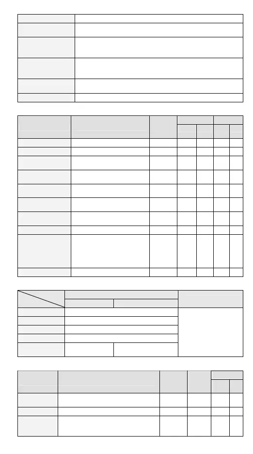
Weight (g) 696
Input Points
Max. input
Model
Terminal Description
Response
char.
Cur. Vol. 20D/
20DT
20M
START0, START1 Enabling input 10 ms 6 mA 24 V
9 9
STOP0, STOP1 Disabling input 10 ms 6 mA 24 V
9 9
LSP0/LSN0,
LSP1/LSN1
Right/left limit input 10 ms 6 mA 24 V
9 9
X1/X2 (for Z axis)
Right/left limit input
(LSP2/LSN2)
10 ms 6 mA 24 V -
9
A0+, A0-, A1+, A1-
(shared by Y/Z axis)
MPG A-phase pulse input +, -
(differential signal input)
200 kHz 15 mA
5 to
24 V
9 9
B0+, B0-, B1+, B1-
(shared by Y/Z axis)
MPG B-phase pulse input +, -
(differential signal input)
200 kHz 15 mA
5 to
24 V
9 9
PG0+, PG0-, PG1+,
PG1-
Zero point signal input +, -
(differential signal input)
200 kHz 15 mA
5 to
24 V
9 9
X3 (for Z axis) Zero point signal input (PG2) 10 ms 6 mA 24 V -
9
DOG0, DOG1
There are 2 variations according
to different operation modes:
1. DOG signal when zero return
2. Inserting enabling signal at
1-seg. or 2-seg. speed
1 ms 6 mA 24 V
9 9
X0 (for Z axis) Same as DOG0, DOG1 (DOG2) 10 ms 6 mA 24 V -
9
Digital Input Points
24 VDC signal common port input
Spec
Item
Low-speed High-speed (200 kHz)
#1
Note
Input wiring type
Change wiring from S/S to SINK or SOURCE
Input indicator LED display; light on = ON, light off = OFF
Input voltage --
Action level OffOn: 20 μs, OnOff: 30 μs
Response time/
noise immunity
#2
10 ms 0.5 μs
#1: Input point A, B, PG is
high-speed input; other
input point is low-speed
input.
#2: Input point X0 to X7
can conduct 10 to 60 ms
digital filter adjustment.
Output Points
Model
Terminal Description
Response
char.
Max.
Cur.
(Input)
20D/
20DT
20M
CLR0+, LR0-,
CLR1+, CLR1-
Clearing signals (by the error counter in
Servo drive)
10 ms 20 mA
9 9
Y2 (for Z axis) Same as clearing signals (CLR2) 10 ms 30 mA -
9
FP0+, FP0-,
FP1+, FP1-
Forward/reverse running mode: Forward
pulse output
Pulse direction: towards pulse output end
500 kHz 40 mA
9 9

 Loading...


