- 3 -
Model
Terminal Description
Response
char.
Max.
Cur.
(Input)
20D/
20DT
20M
FP2+, FP2-
A, B phase: A-phase output
(FP2+、FP2- are for Z axis pulse output)
500 kHz 40 mA -
9
RP0+, RP0-,
RP1+, RP1-
9 9
RP2+, RP2-
Forward/reverse running mode: Reverse
pulse output
Pulse direction: towards output end
A, B phase: B-phase output
(RP2+, RP2- are for Z axis pulse output)
500 kHz 40 mA
-
9
Digital Output Points
Single common port transistor output
#1
Spec
Item
Low-speed
Single common port relay
output
#1
Max. frequency
10 kHz For load ON/OFF control
Output indicator LED display; light on = ON, light off = OFF
Min. load -- 2mA/DC power supply
Working voltage 5 to 30 VDC < 250 VAC, 30 VDC
Insulation Photo coupler isolation Electromagnetic isolation
Resistive 0.5 A/1 point (4A/COM) 2 A/1 point (5 A/COM)
Inductive 12 W (24 VDC)
#2
Maximum
load
Lamp 2 W (24 VDC) 20 WDC/100 WAC
OffOn 20 μs
#2
Max. output
delay time
OnOff 30 μs
#2
10 ms
Over-current
protection
N/A
#1: For DVP20PM00D, Y0 to Y7 are relay output terminals. For DVP20PM00M, Y2 and Y3 are
low speed transistor output terminals and Y4 to Y7 are relay output terminals. For
DVP20PM00DT, Y0 to Y7 are low speed transistor output terminals.
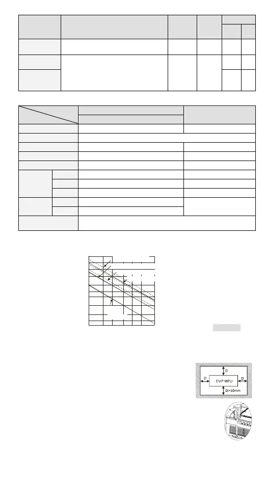
#2: Life curves
Contact Current (A)
0.50.1 0.2
30
50
0.3 0.7 1 2
200
300
500
100
1,000
2,000
3,000
O
p
e
r
a
t
io
n
(
X
1
0
3
120 VAC Resistive
30 VDC Inductive(t = 7 ms)
240 VAC Inductive(cos 0.4)
ψ
=
120 VAC Inductive(cos = 0.4)
ψ
30 VDC
Inductive
(t = 40 ms)
[ Figure 4 ]
#3: Load = 0.5A
Installation
Please install the PLC in an enclosure with sufficient space
around it to allow heat dissipation, as shown in the figure.
y Direct Mounting: Please use M4 screw according to the
dimension of the product.
y DIN Rail Mounting: When mounting the PLC to 35mm DIN
rail, be sure to use the retaining clip to stop any side-to-side movement
of the PLC and reduce the chance of wires being loose. The retaining
clip is at the bottom of the PLC. To secure the PLC to DIN rail, pull down
the clip, place it onto the rail and gently push it up. To remove the PLC,
pull the retaining clip down with a flat screwdriver and gently remove the
PLC from DIN rail, as shown in the figure.
Wiring

 Loading...


