DVP-ES2/EX2/EC5/SS2/SA2/SX2/SE&TP Operation Manual - Programming
-158
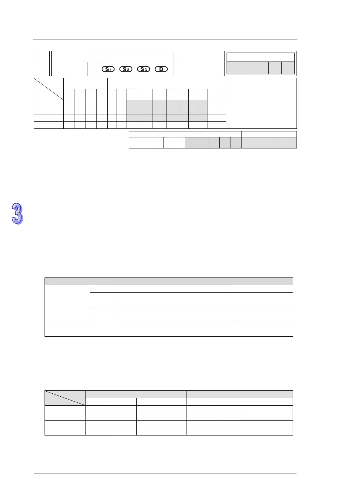
API
Mnemonic Operands Function
59 D
PLSR
Pulse Ramp
Type
OP
Bit Devices Word devices Program Steps
X Y M S K H KnX
KnY
KnM
KnS
T C D E F
PLSR: 9 steps
DPLSR: 17 steps
SS2
SX2
SS2
SX2
SS2
SX2
Operands:
S
1
: Maximum frequency (Hz) S
2
: Number of pulses S
3
: Ramp up/down time (ms)
D: Pulse output device (Y0, Y1, Y2, Y3, Y4 and Y6 are available) (EC5/DVP-12SE: FW V1.xx does
not support Y1 and Y3.)
Explanations:
(For ES2 / EX2 / SS2 / SA2 / SE / SX2 Series PLC CPU)
1. PLSR instruction performs a frequency ramp up/down process when positioning. Speed ramp
up process is activated between static status to the target speed. Pulse output persists in target
speed before getting close to target position. When target position is near, speed ramp down
process executes, and pulse output stops when target position is achieved.
2. Set range of S
1
pulse output frequency:
Range of S
1
pulse output frequency:
Output
frequency:
16-bit
SS2: 6~10,000Hz
ES2/EX2/SA2/SX2/SE: 6~32,767Hz
6~10,000Hz
32-bit
SS2: 6~10,000Hz
ES2/EX2/SA2/SX2/SE: 0~100,000Hz
6~10,000Hz
If frequency smaller than 6Hz is specified, PLC will output 6Hz.
If frequency bigger than max frequency is specified, PLC will output with max frequency.
3. When output device is specified with Y0, Y2, the start/end frequency of Y0 is set by D1340 and
start/end frequency of Y2 is set by D1352.
4. When output device is specified with Y1, Y3, the start/end frequency is 0Hz.
5. When D1220/D1221 = K1 or K2, positive/negative sign of S2 denotes pulse output direction.
6. PLSR instruction supports two modes of pulse output as below list.
PLSR instruction does NOT support the value of pulse=0, e.g. infinite pulse output.