4. Communications
Default communication settings for all COM ports:
− Modbus ASCII
− 7 data bits
− 1 stop bit
− Odd parity
− Baud rate: 9600
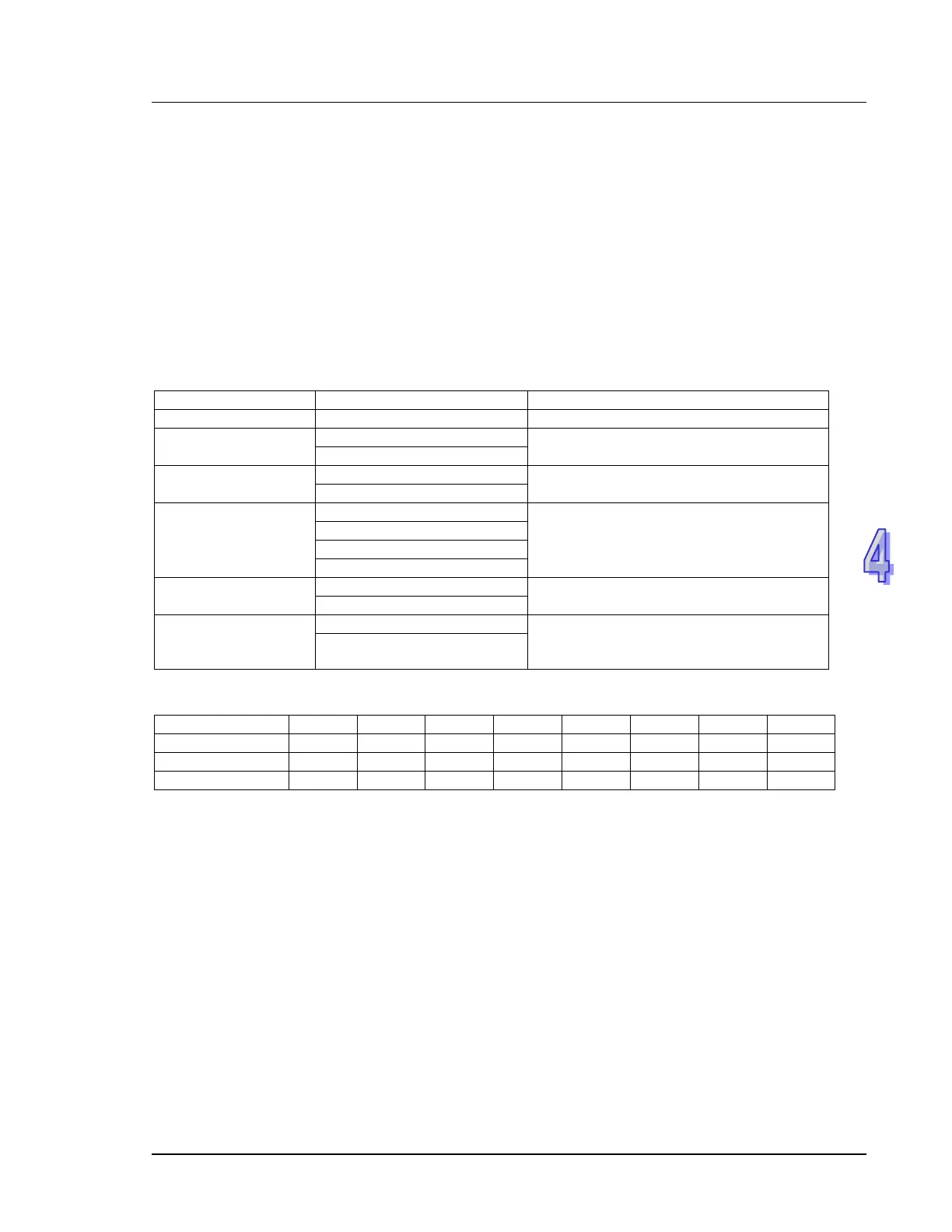
4.2 Communication Protocol ASCII mode
Communication Data Structure
9600 (Baud rate), 7 (data bits), Even (Parity), 1 (Start bit), 1 (Stop bit)
Address consists of 2 ASCII codes
Command code
Command code consists of 2 ASCII
codes
Data
Data content consist of 2n ASCII codes,
n≤205
LRC checksum
LRC checksum consists of 2 ASCII codes
Stop bit
Stop bit consists of 2 ASCII codes
END1 = CR (0DH),
END0
Corresponding table for Hexadecimal value and ASCII codes
4.2.1 ADR (Communication Address)
Valid communication addresses are in the range of 0~254. Communication address equals to 0 means
broadcast to all PLCs. PLC will not respond to a broadcast message. PLC will reply a normal message
to the master device when communication address is not 0.
Example, ASCII codes for communication address 16 in Decimal. (16 in Decimal = 10 in Hex)
(ADR 1, ADR 0)=’1’,’0’’1’=31H, ‘0’ = 30H