DVP-ES2/EX2/EC5/SS2/SA2/SX2/SE&TP Operation Manual - Programming
-160
16. Set value falls out of the available range of operands will be automatically corrected with the
min. or max available value.
17. When M1334 or M1335 is enabled, execute API59 PLSR/DPLSR instructions on Y0 or Y2
to ramp-down when the conditional contacts are closed. When the conditional contacts are
closed, the deceleration will stop and the flags M1334/M1335 will be cleared. After the
conditional contacts are closed, if you need to use the flags M1334/M1335 to stop the
deceleration, you need to enable the flags M1334/M1335 again.
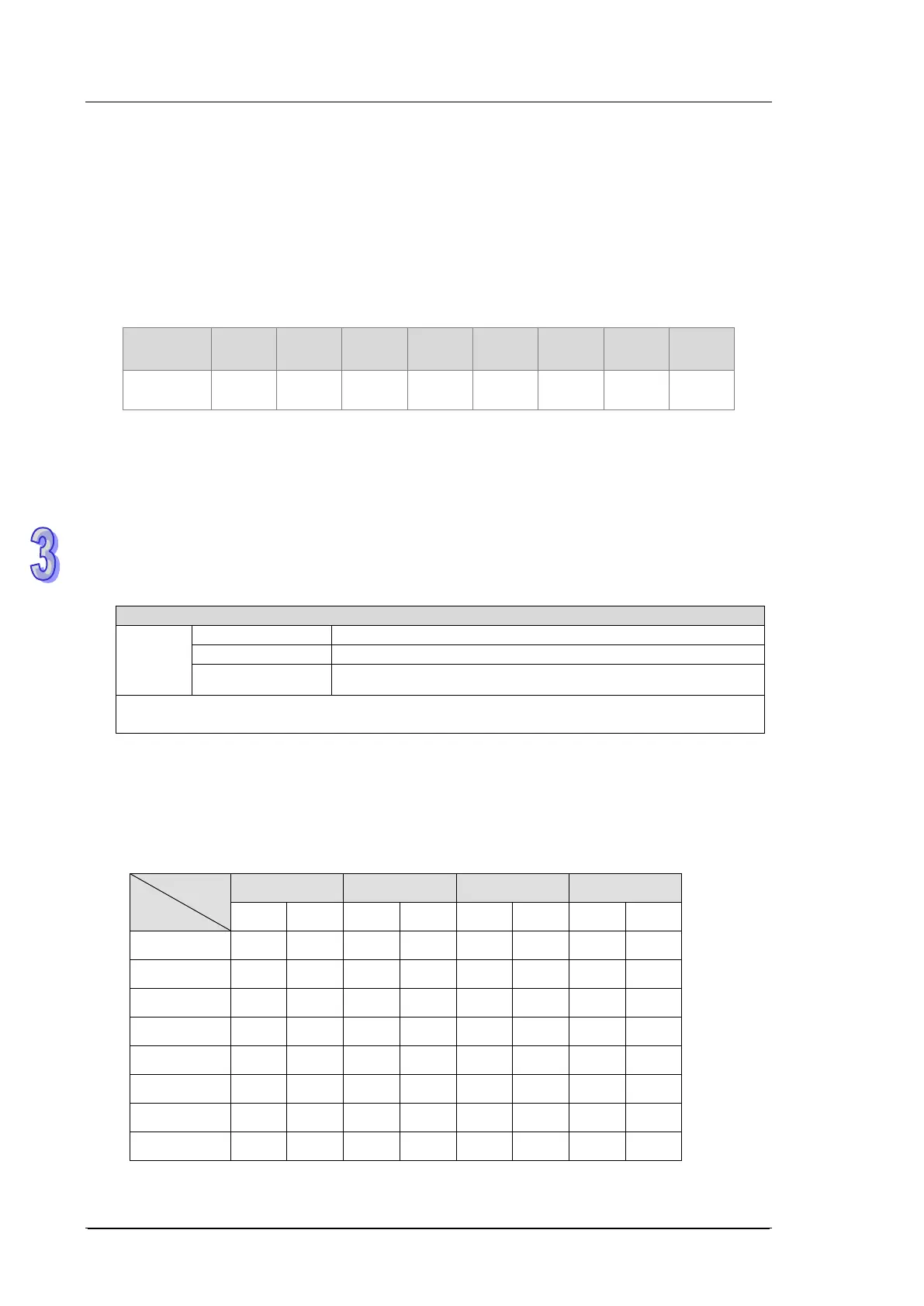
Series
ES2-C ES2-E
SS2 12SE 26SE 28SA2
V3.42 V3.48 V1.00 V2.86 V3.28 V2.02 V1.0 V2.90
(For EC5 Series PLC CPU)
1. PLSR instruction performs a frequency ramp up/down process when positioning. Speed ramp
up process is activated between static status to the target speed. Pulse output persists in
target speed before getting close to target position. When target position is near, speed ramp
down process executes, and pulse output stops when target position is achieved.
2. Set range of S
1
pulse output frequency:
Output frequency range of EC5 Series PLC CPU
range
32-bit instruction 6~50,000 Hz
If frequency equals or smaller than 6Hz is specified, pulse output will be disabled.
If frequency bigger than max frequency is specified, PLC will output with max frequency.
3. When output device is specified with Y0, Y2, Y4, Y6, the start/end frequency of Y0 is set by
D1340, of Y2 by D1352, of Y4 by D1379, and of Y6 by D1380.
4. When D1220/D1221/D1341/D1342= K0, K1,or K2, the positive/negative sign of S
2
denotes
pulse output direction (Positive/negative).
5. Four pulse output modes:
Mode
Output
D1220 D1221 D1341 D1342
K0 K1 K0 K1 K0 K1 K0 K1
Y0 Pulse Pulse
Y1 Dir
Y2 Pulse Pulse
Y3 Dir
Y4 Pulse Pulse
Y5 Dir
Y6 Pulse Pulse
Y7 Dir
PLSR instruction does NOT support the value of pulse=0, e.g. infinite pulse output.