1. PLC Concepts
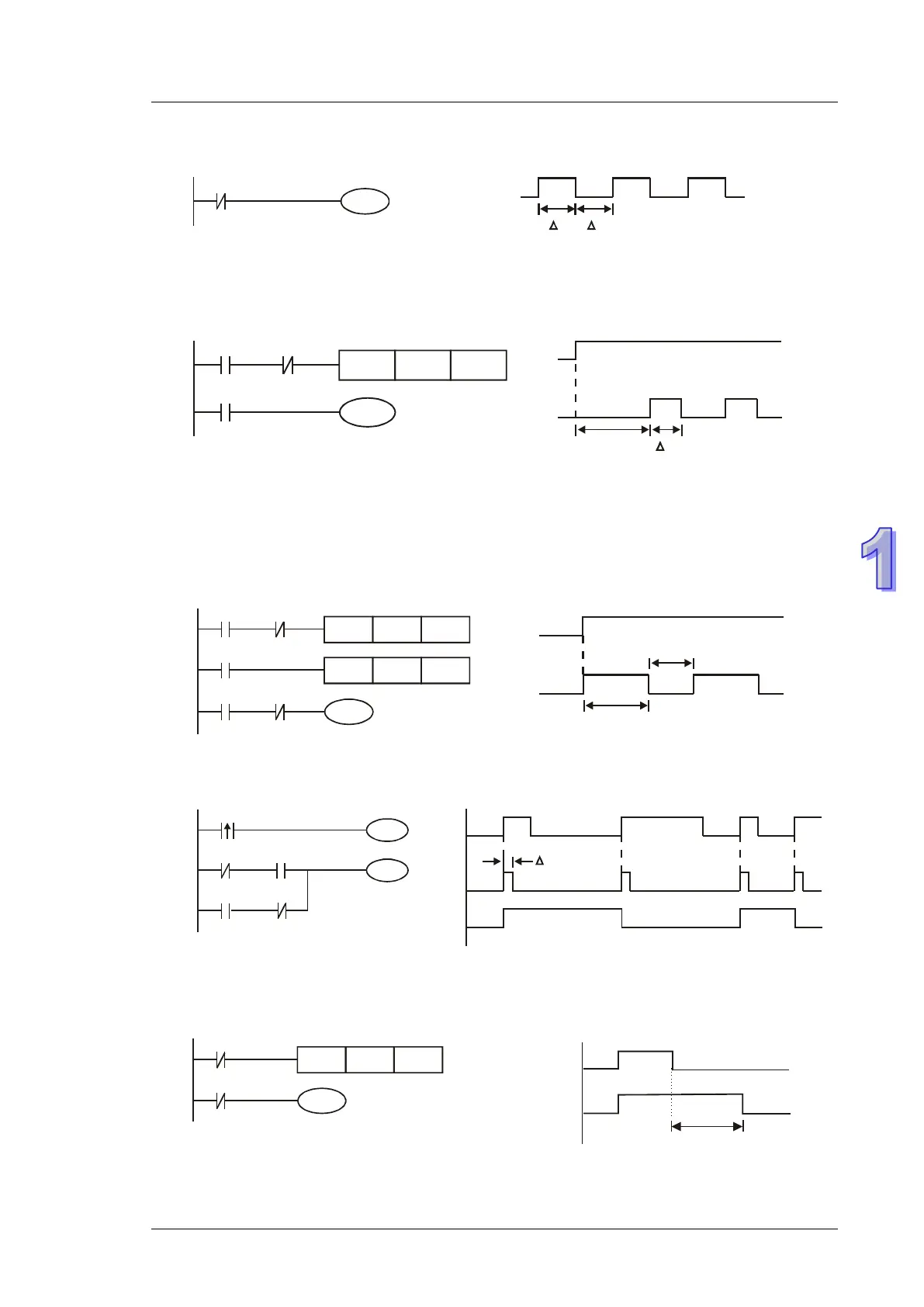
Example 8 - Oscillating Circuit
An oscillating circuit with cycle ΔT+ΔT
In the first scan, Y1 turns on. In the second scan, Y1 turns off due to the reversed state of contact
Y1. Y1 output status changes in every scan and forms an oscillating circuit with output
cycleΔT(ON)+ΔT(OFF)
Example 9 – Oscillating Circuit with Timer
An oscillating circuit with cycle nT+ΔT
When X0 = ON, T0 starts timing (nT). Once the set time is reached, contact T0 = ON to enable
Y1(ΔT). In next scan, Timer T0 is reset due to the reversed status of contact Y1. Therefore contact
T0 is reset and Y1 = OFF. In next scan, T0 starts timing again. The process forms an oscillating
circuit with output cycle nT+ΔT.
Example 10 - Flashing Circuit
The ladder diagram uses two timers to form an oscillating circuit which enables a flashing indicator
or a buzzing alarm. n1 and n2 refer to the set values in T1 and T2 and T refers to timer resolution.
T2TMR Kn2
T1
X0
TMR
Y1
T2
T1
Kn1
X0 T1
Example 11 - Trigger Circuit
In this diagram, rising-edge contact X0 generates trigger pulses to control two actions executing
interchangeably.
Example 12 - Delay OFF Circuit
If X0 = ON, timer T10 is not energized but coil Y1 is ON. When X0 is OFF, T10 is activated. After
100 seconds (K1000 × 0.1 sec = 100 sec), NC contact T10 is ON to turn off Y1. Turn-off action is
delayed for 100 seconds by this delay OFF circuit.
Timer Resolution: 0.1 sec