3. Instruction Set
3-237
API
Mnemonic Operands Function
74 SEGL
7-segment with Latch
Type
OP
Bit Devices Word devices Program Steps
X Y M S K H KnX
KnY
KnM
KnS
T C D E F
SEGL: 7 steps
SS2
SX2
SS2
SX2
SS2
SX2
Operands:
S: Source device storing the value to be displayed in 7-segment display D: Output device for
7-segment display
n: Configuration setting of output signal (n = 0~7)
Explanations:
1. This instruction occupies 8 or 12 consecutive external output points starting from D for
displaying the data of 1 or 2 sets of 4-digit 7-segment display. Every digit of the 7-segment
display carries a “Drive” which converts the BCD codes into 7-segment display signal. The drive
also carries latch control signals to retain the display data of 7-segment display.
2. n specifies the number of sets of 7-segment display (1 set or 2 sets ), and designates the
positive / negative output of PLC and the 7-segment display.
3. When there is 1 set of 4-digit output, 8 output points will be occupied. When there are 2 sets of
4-digit output, 12 output points will be occupied
4. When the instruction is executed, the output terminals will be scanned circularly. When the drive
contact goes from OFF to ON again during the execution of instruction, the scan will restart from
the beginning of the output terminals.
5. Flag: When SEGL is completed, M1029 = ON for one scan cycle.
6. There is no limitation on the times of using this instruction in the program, however only one
instruction is allowed to be executed at a time.
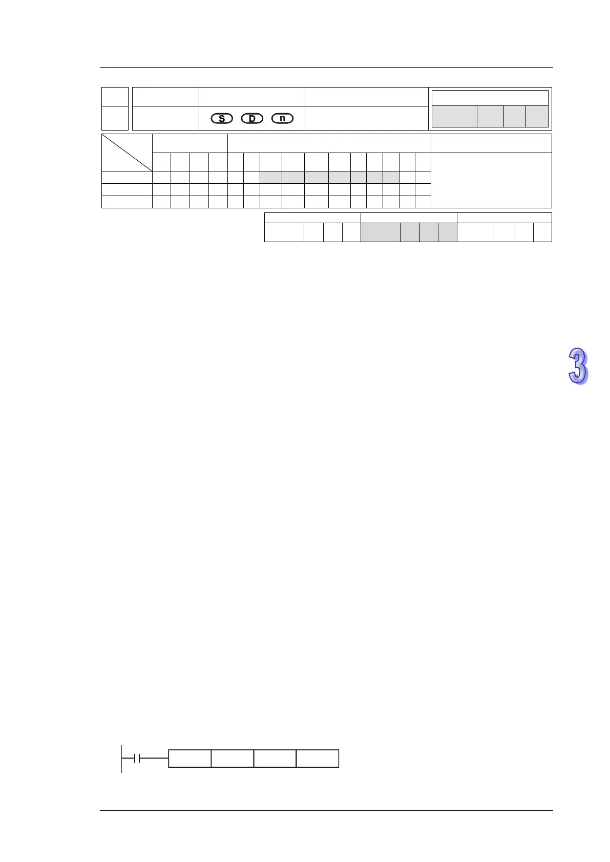
Program Example:
1. When X20 = ON, SEGL instruction executes and Y24~Y27 forms an output scan loop for
7-segment display. The value of D10 will be mapped to Y20~Y23, converted to BCD code and
sent to the 1st set of 7-segment display. The value of D11 will be mapped to Y30~Y33,
converted to BCD code and sent to the 2
nd
set of 7-segment display. If the values in D10 and
D11 exceed 9,999, operational error will occur.