3. Instruction Set
3-247
communication port
108 0~255 1~(256-m2)
NOT recommended
* m
1
=108 indicates the parameter of the PLC CPU built-in network communication port. Refer to
Appendix B.2 for more information on CR.
SS2:
Operand m1 m2
n in the 16-bit
instruction
n in the 32-bit
instruction
Right-side module 0~7 0~48
1~4,
1~6 (V2.8 and above)
1~2,
1~3 (V2.8 and above)
Left-side modules are not supported.
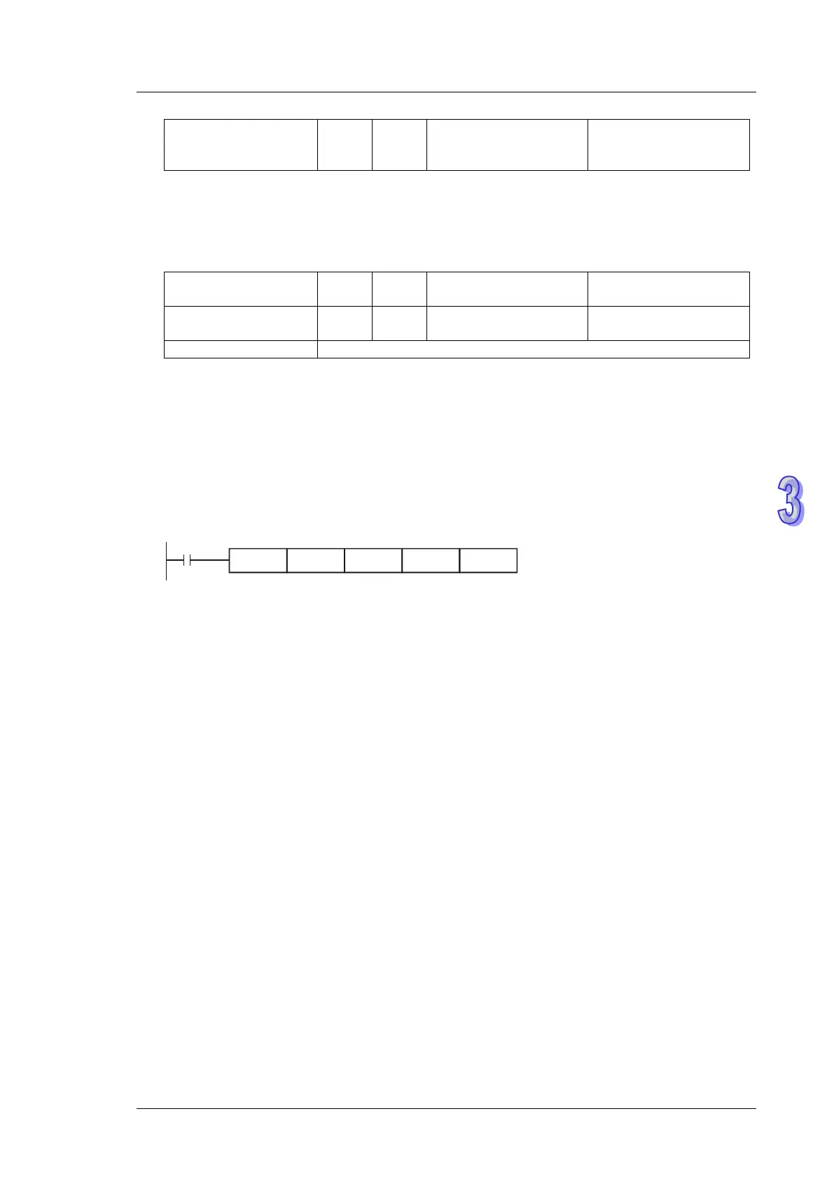
Program Example:
1. Read out the data in CR#29 of special module N0.0 to register D0 in PLC, and CR#30 of
special module No.0 to register D1 in PLC. 2 consecutive 16-bit data are read at one time (n =
2).
2. When X0 = ON, the instruction executes; when X0 = OFF, the previous content in D0 and D1
won’t be changed.