3. Instruction Set
3-265
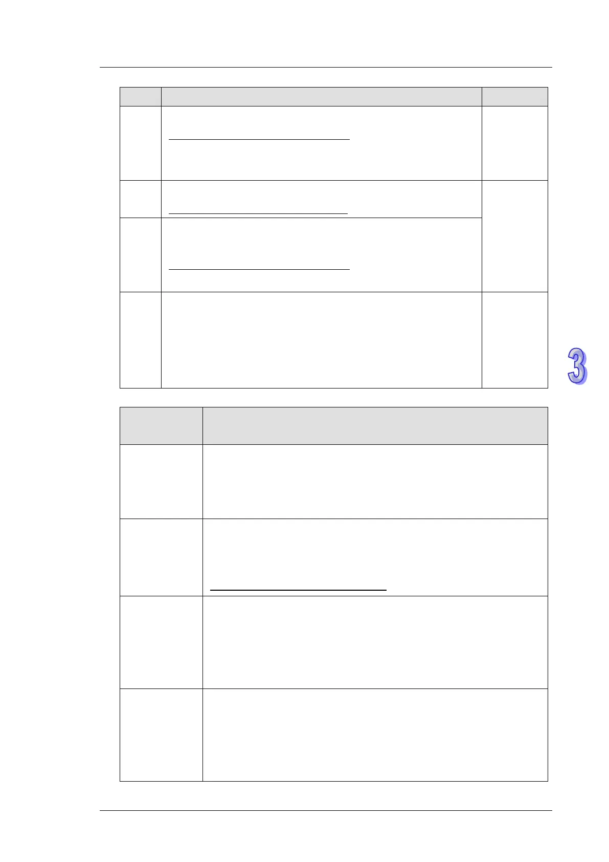
Flag Function Action
M1143
ASCII / RTU mode selection. ON : RTU mode, OFF: ASCII mode.
Supported communication instructions:
RS / MODRD / MODWR / MODRW (When M1177 = ON, FWD /
REV / STOP / RDST / RSTEF can also be applied.
User sets
and resets
M1161
8/16-bit mode. ON: 8-bit mode. OFF: 16-bit mode
Supported communication instructions: R
S
User sets
M1177
Enable the communication instruction for Delta VFD series inverter.
ON: VFD-A (Default), OFF: other models of VFD
Supported communication instructions:
FWD / REV / STOP / RDST / RSTEF
M1263
Execute RS instruction with M1263 to set the data receiving as
completed, when the data receiving stops for a period of time that is
longer than what D1168 was set (The specific end word to be
detected for RS instruction to execute an interruption request). If the
receiving is not started, the detecting will not be started either.
and
system
resets
Special
register
Function
D1038
Delay time of data response when PLC is SLAVE in COM2, COM3
RS-485 communication, Range: 0~10,000. (Unit: 0.1ms).
By using EASY PLC LINK in COM2, D1038 can be set to send next
communication data with delay. (unit: one scan cycle)
D1050~D1055
Converted data for Modbus communication data processing. PLC
automatically converts the ASCII data in D1070~D1085 into Hex data
and stores the 16-bit Hex data into D1050~D1055
Supported communication instructions: M
ODRD / RDST
D1070~D1085
Feedback data (ASCII) of Modbus communication. When PLC’s RS-485
communication instruction receives feedback signals, the data will be
saved in the registers D1070~D1085 and then converted into Hex in
other registers.
RS instruction is not supported.
D1089~D1099
Sent data of Modbus communication. When PLC’s RS-485
communication instruction (MODRD) sends out data, the data will be
stored in D1089~D1099. Users can check the sent data in these
registers.
RS instruction is not supported