3. Instruction Set
3-275
Function code:
03 H: read contents from multiple registers
06 H: write one word into single register
10 H: write contents to multiple registers
Data characters:
The data sent by the user
CRC checksum: Starting from Address and ending at Data Content. The calculation is as follows:
Step 1: Set the 16-bit register (CRC register) = FFFFH
Step 2: Operate XOR on the first 8-bit message (Address) and the lower 8 bits of CRC register.
Store the result in the CRC register.
Step 3: Right shift CRC register for a bit and fill “0” into the highest bit.
Step 4: Check the lowest bit (bit 0) of the shifted value. If bit 0 is 0, fill in the new value obtained at
step 3 to CRC register; if bit 0 is NOT 0, operate XOR on A001H and the shifted value and store the
result in the CRC register.
Step 5: Repeat step 3 – 4 to finish all operation on all the 8 bits.
Step 6: Repeat step 2 – 5 until the operation of all the messages are completed. The final value
obtained in the CRC register is the CRC checksum. Care should be taken when placing the LOW
byte and HIGH byte of the obtained CRC checksum.
Example:
Read 2 continuous data stored in the registers of the drive at address 01H (see the table below).
The start register is at address 2102H
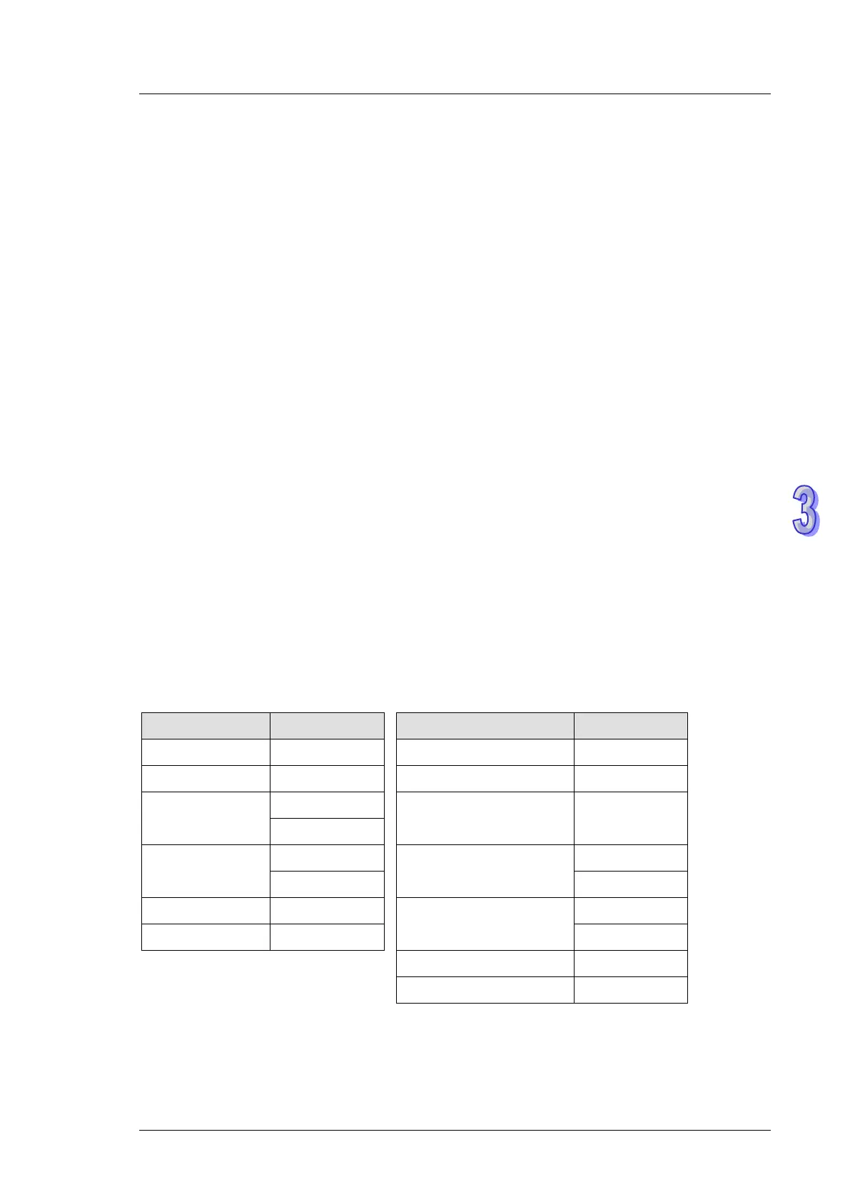
Inquiry message: Response message:
Field Name Data (Hex) Field Name Data (Hex)
Address 01 H Address 01 H
Function 03 H Function 03 H
Start data
address
21 H
Number of data
(count by byte)
04 H
02 H
Number of data
(count by word)
00 H
Content of data address
2102H
17 H
02 H 70 H
CRC CHK Low 6F H
Content of data address
2103H
00 H
CRC CHK High F7 H 00 H
CRC CHK Low FE H
CRC CHK High 5C H