3. Instruction Set
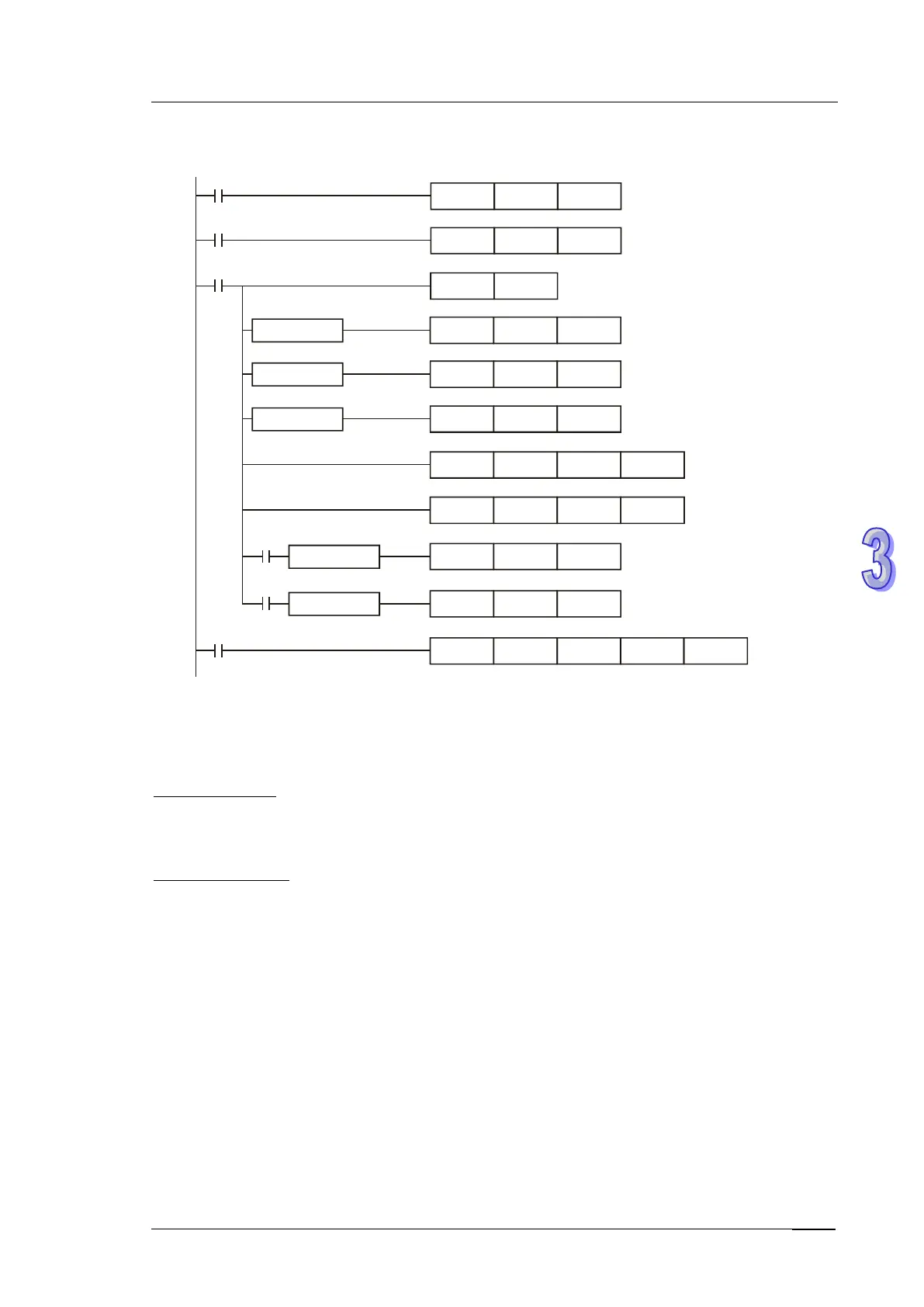
Example program of SV ramp up function:
M1002
MOV K10 D3
M10
M0
TMR T0 D3
T0
RST
T0
MOV K50 D2
D1D0>
MOV
K-50
D2
D1D0<
MOV K0 D2
D1D0=
ADD D2 D1 D1
CMP D2 K0
M10
D0D1
<
MOV D0 D1
M12
D0D1
>
MOV D0
D1
M0
PID D1 D1116 D10 D5
Application 2:
Speed control system and pressure control system work individually (use diagram of Example 2)
C
ontrol purpose:
After the speed control operates in open loop for a period of time, adding pressure control system
(PID instruction) to perform a close loop control.
Control properties:
Since the speed and pressure control systems are not interrelated, we have to structure an open
loop for speed control first following by a close loop pressure control. If users afraid that the
pressure control system changes excessively, consider adding the SC ramp-up function illustrated
in Application 1 into this control. See the control diagram below.