EasyManuals Logo
Home>Delta>Controller>DVP-SS2

Delta DVP-SS2 User Manual

Delta DVP-SS2
1006 pages
To Next Page IconTo Next Page
To Previous Page IconTo Previous Page
Page #452 background imageLoading...
Page #452 background image
3. Instruction Set
3-331
Registers for received data (responding messages)
Register
Data
Descriptions
D1070 low
‘0’
30 H
ADR 1
D1070 high
‘1’
31 H
ADR 0
D1071 low
‘0’
30 H
CMD 1
D1071 high
‘6’
36 H
CMD 0
D1072 low
‘0’
30 H
Data address
D1072 high
‘1’
31 H
D1073 low
‘0’
30 H
D1073 high
‘0’
30 H
D1074 low
‘1’
31 H
Data content
D1074 high
‘7’
37 H
D1075 low
‘7’
37 H
D1075 high
‘0’
30 H
D1076 low
‘7’
37 H
LRC CHK 1
D1076 high
‘1’
31 H
LRC CHK 0
Program Example 2:
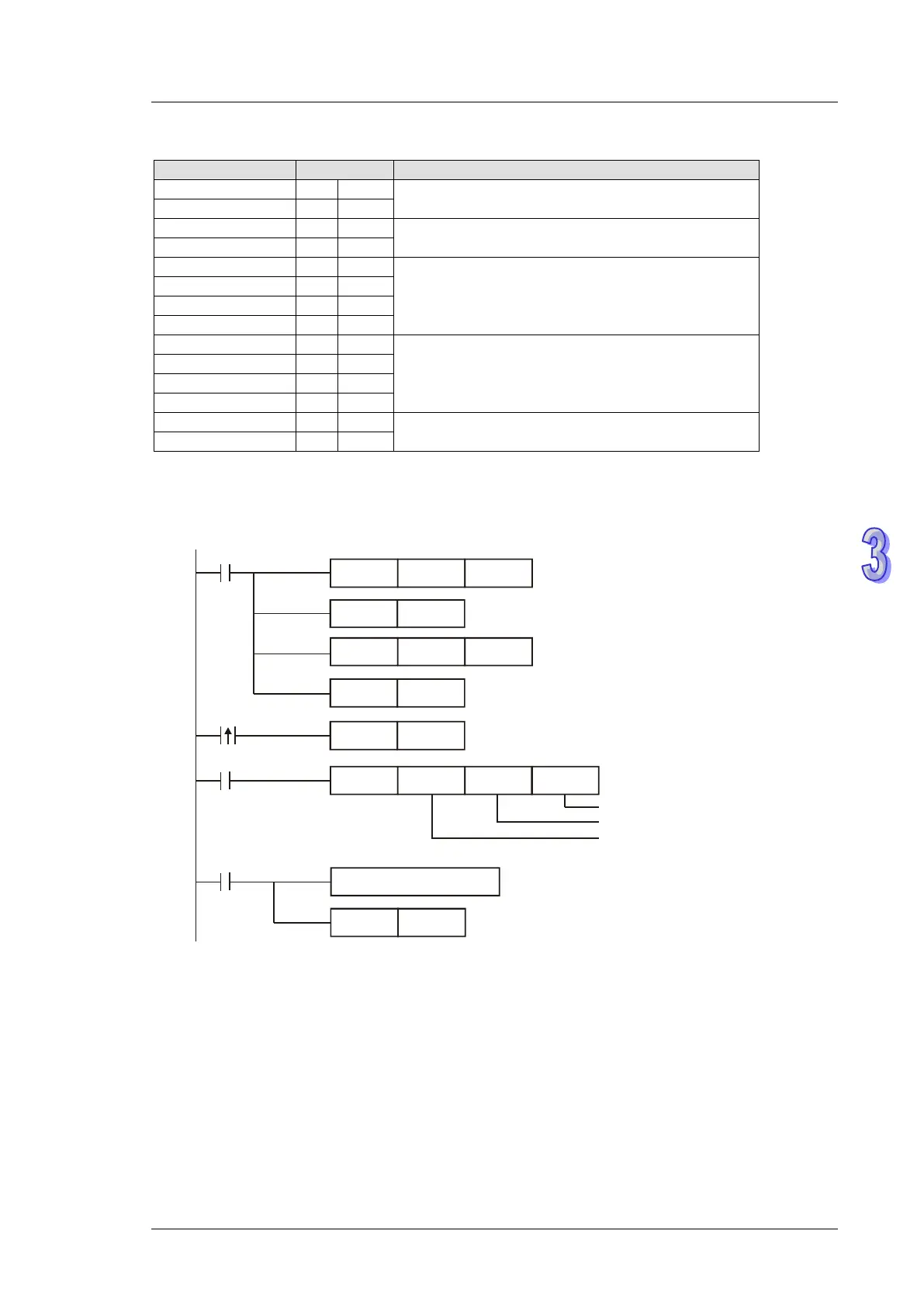
Communication between PLC and VFD-B series AC motor drives (RTU Mode, M1143 = ON)
MOV D1120
H87
M1002
SET M1120
Set communication protocol as 9600, 8, E, 1
Retain communication protocol
Set receiving timeout as 100ms
Sending request
X1
M1127
RST M1127
Receiving
completed
Process of receiving data
Reset M1127
The receiving data is stored in
D1070~D1085 in Hex.
Set as RTU mode
X0
Set communication instruction:
Data address: H2000
Write in data H12
Device address: 01
MOV D1129
K100
SET
M1143
SET M1122
MODWR H2000K1 H12
PLC → VFD-B, PLC transmits: 01 06 2000 0012 02 07
VFD-B → PLC, PLC receives: 01 06 2000 0012 02 07

Table of Contents

Other manuals for Delta DVP-SS2

Questions and Answers:

Question and Answer IconNeed help?

Do you have a question about the Delta DVP-SS2 and is the answer not in the manual?

Delta DVP-SS2 Specifications

General IconGeneral
BrandDelta
ModelDVP-SS2
CategoryController
LanguageEnglish

Related product manuals