3. Instruction Set
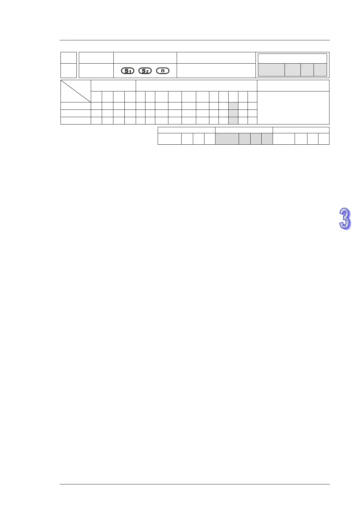
API
Mnemonic Operands Function
104 STOP
Stop VFD
Type
OP
Bit Devices Word devices Program Steps
X Y M S K H KnX
KnY
KnM
KnS
T C D E F
STOP: 7 steps
SS2
SX2
SS2
SX2
SS2
SX2
Operands:
S
1
: Device address S
2
: Operation frequency of VFD n: Operation mode
Explanations:
1. M1177 = OFF (Default), FWD, REV, STOP instructions support COM2(RS-485).
2. M1177= ON, FWD, REV, STOP instructions support COM2(RS-485), COM3(RS-485).
3. M1177 has to be set up in advance for selecting the target model of VFD. When M1177 = OFF
(Default), FWD, REV, STOP instructions support Delta’s VFD-A inverter. When M1177 = ON,
these instructions support other models of VFD inverters, e.g. VFD-B, VFD.
4. There is no limitation on the times of using FWD, REV, STOP instruction, however only one
instruction can be executed on single COM port at a time.
5. If rising-edge (LDP, ANDP, ORP) or falling-edge (LDF, ANDF, ORF) contacts are used before
FWD, REV, STOP instructions, sending request flags M1122 (COM2) / M1316 (COM3) has to
be enabled in advance for obtaining correct operation.
6. For detailed information of associated flags and special registers, please refer to RS instruction.
7. M1177 = OFF, only Delta VFD-A is supported and the definition of each operand is:
a) S
1
= Address of VFD-A. Range of S
1
: K0 ~ K31
b) S
2
= Operation frequency of VFD. Set value for VFD A-type inverter: K0 ~ K4,000 (0.0Hz
~ 400.0Hz).
c) n = Communication mode. Range: K1 ~ K2. n = 1: communicate with VFD at designated
address. n = 2: communicate with all connected VFDs. .
d) The feedback data from the peripheral equipment will be stored in D1070 ~ D1080 After
data receiving is completed, PLC will check if all data are correct automatically. If there is
an error, M1142 will be ON. When n = 2, PLC will not receive any data.