3. Instruction Set
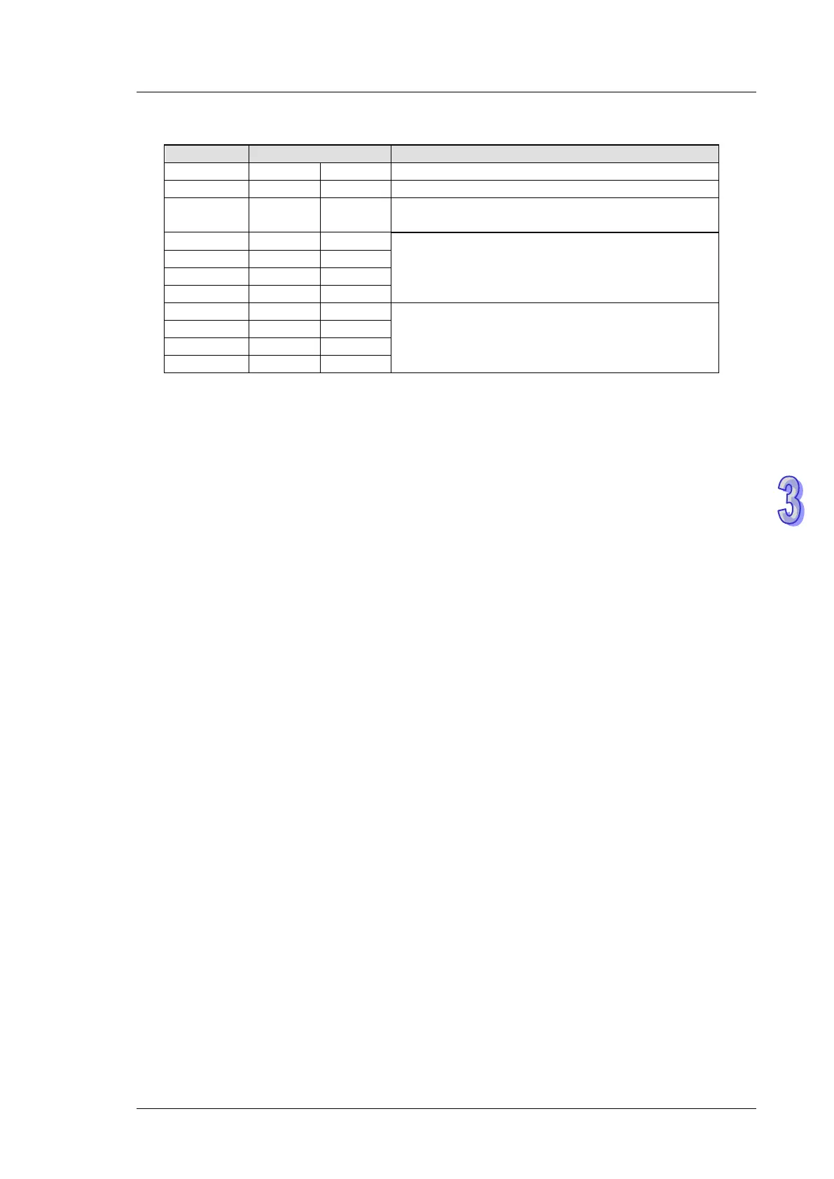
Registers for received data (responding messages)
D1072 low ‘♠’ 06 H
Acknowledge back. (Check feedback data)
(correct: 06H, Error: 07 H)
Communication address
Operation command
2. M1177 = ON, other Delta VFDs are supoported
a) S
1
= Address of VFD-A. Range of S
1
: K0 ~ K255, when S
1
is specified as K0, PLC will
broadcast to all connected VFDs.
b) S
2
= Running frequency of VFD. Please refer to manuals of specific VFD. In STOP
instruction, operand S
2
is reserved.
c) n = Operation mode.
In FWD instruction: n = 0 Forward mode; n = 1 Forward JOG. Other values will
be regarded as normal forward mode.
In REV instruction: n = 0 Reverse mode; n = 1 Reverse JOG. Other values will
be regarded as normal reverse mode
In STOP instruction: operand n is reserved.
d) When Forward JOG is selected in FWR instruction, set value in S
2
is invalid. If users need
to modify the JOG frequency, please refer to manuals of specific VFDs.