2. Programming Concepts
D
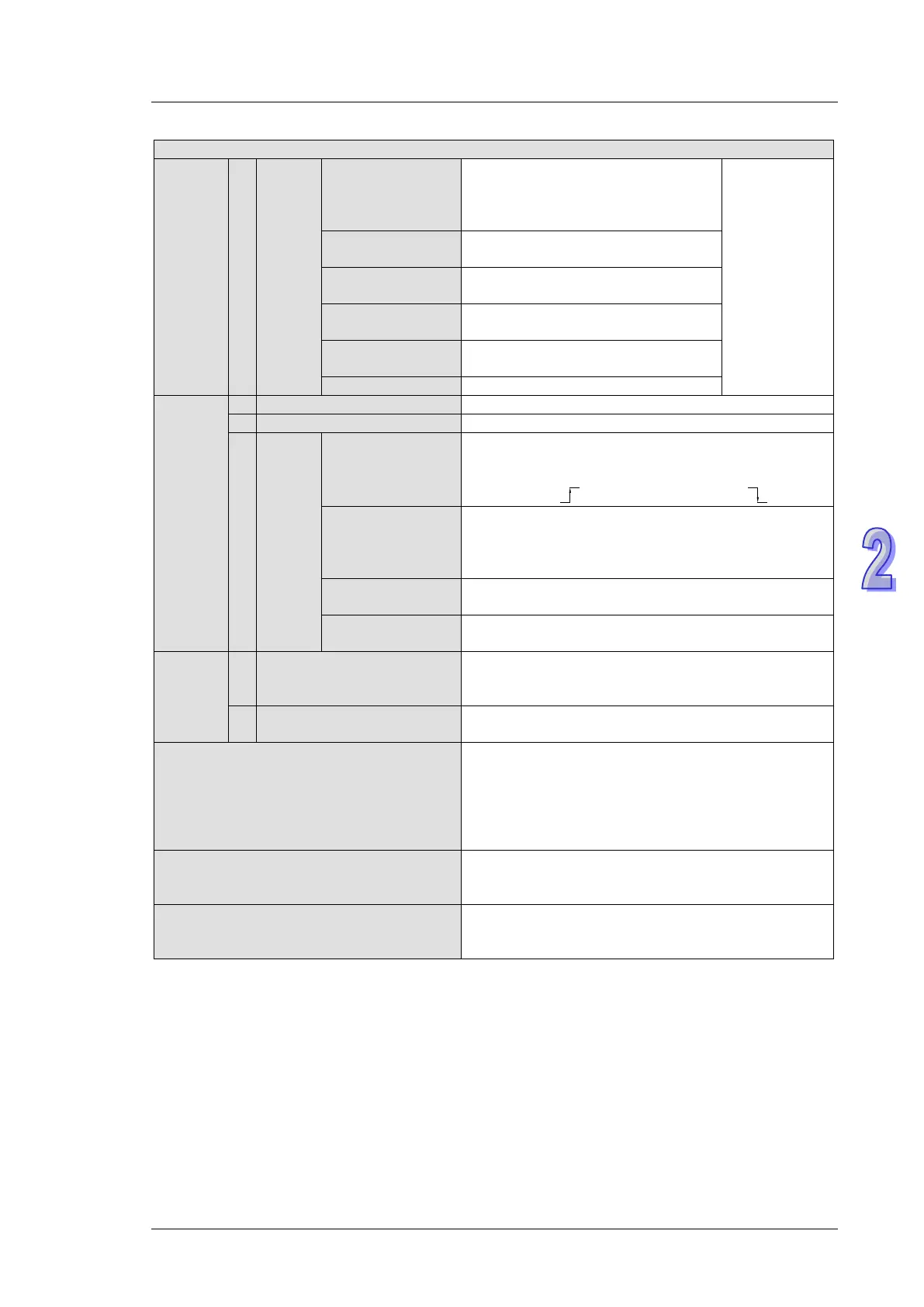
Data
register
General
D600~D999, 400 words, (*1)
D3920~D9799, 5880 words, (*1)
D10000~D11999, 2000 words, (*1)
Total
12000 points
Latched
D408~D599, 192 words, (*2)
D2000~D3919, 1920 words, (*2)
Special
D1000~D1999, 1000 words, some
are latched
Right-side special
module
D9900~D9999, 100 words, (*1) (*5)
D9800~D9899, 100 words, (*1) (*6)
(NOT applicable to DVP26SE)
E0~E7, F0~F7, 16 words, (*1)
Pointer
I
Service
External interrupt
I000/I001(X0), I100/I101(X1), I200/I201(X2),
I300/I301(X3), I400/I401(X4), I500/I501(X5),
I600/I601(X6), I700/I701(X7), 8 points (01: rising-
edge trigger , 00: falling-edge trigger )
Timer interrupt
I602~I699, I702~I799, 2 points (Timer resolution =
1ms)
I805~I899, 1 point (Timer resolution = 0.1ms)
(Supported by V1.60 and above)
High-speed
counter interrupt
I010, I020, I030, I040, I050, I060, I070, I080, 8
points
I150 (COM2), I160 (COM3), 2 points, (*3)
Constant
K Decimal
K-32,768 ~ K32,767 (16-bit operation),
K-2,147,483,648 ~ K2,147,483,647 (32-bit
H Hexadecimal
H0000 ~ HFFFF (16-bit operation),
H00000000 ~HFFFFFFFF (32-bit operation)
Serial Ports
COM1: built-in USB (Slave)
COM2: built-in RS-485 (Master/Slave)
COM3: built-in RS-485 (Master/Slave)
Ethernet: built-in Ethernet (Please refer to Appendix
B for more information.)
COM1 is typically the programming port.
Real Time Clock
Year, Month, Day, Week, Hours, Minutes, Seconds;
When the power is off, this function can still go on
Special I/O Modules
Right side: Up to 8 I/O modules can be connected.
Left side: Up to 8 high-speed I/O modules can be
Notes:
1. Non-latched area cannot be modified.
2. Latched area cannot be modified.
3. COM2: built-in RS485 port. COM3: built-in RS485 port.
4. The PLC occupies 16 input points (X0~X17) and 16 output points (Y0~Y17). The extension
input point starts from X20 and extension output point from Y20.
5. If an SE series MPU is connected to a right-side special module, and M1183 is Off, the data
registers can be used. Each connected special module occupies ten data registers.
6. If an SE series MPU is connected to a left-side special module, and M1182 is Off, the data
registers can be used. Each connected special module occupies ten data registers.