DVP-ES2/EX2/EC5/SS2/SA2/SX2/SE&TP Operation Manual - Programming
Program example 6: COM1(RS-232) / COM3(RS-485), Function Code H05
1. Function Code K5 (H05): Force ON/OFF bit device.
2. PLC1 connects PLC2: (M1320 = OFF, ASCII Mode ), (M1320 = ON, RTU Mode)
3. n = 1 indicates Force ON (set FF00H) and n = 0 indicates Force OFF (set 0000H)
4. PLC COM1/COM3 will not process the received data.
5. Take the connection between PLC1 (PLC COM3) and PLC2(PLC COM1) for example, the
tables below explains the status when PLC1 reads Y0~Y17 of PLC2
If PLC1 applies COM1 for communication, the below program can be usable by changing:
a) D1109→D1036: communication protocol
b) M1136→M1138: retain communication setting
c) D1252→D1249: Set value for data receiving timeout
d) M1320→M1139: ASCII/RTU mode selection
e) M1316→M1312: sending request
f) M1318→M1314: receiving completed flag
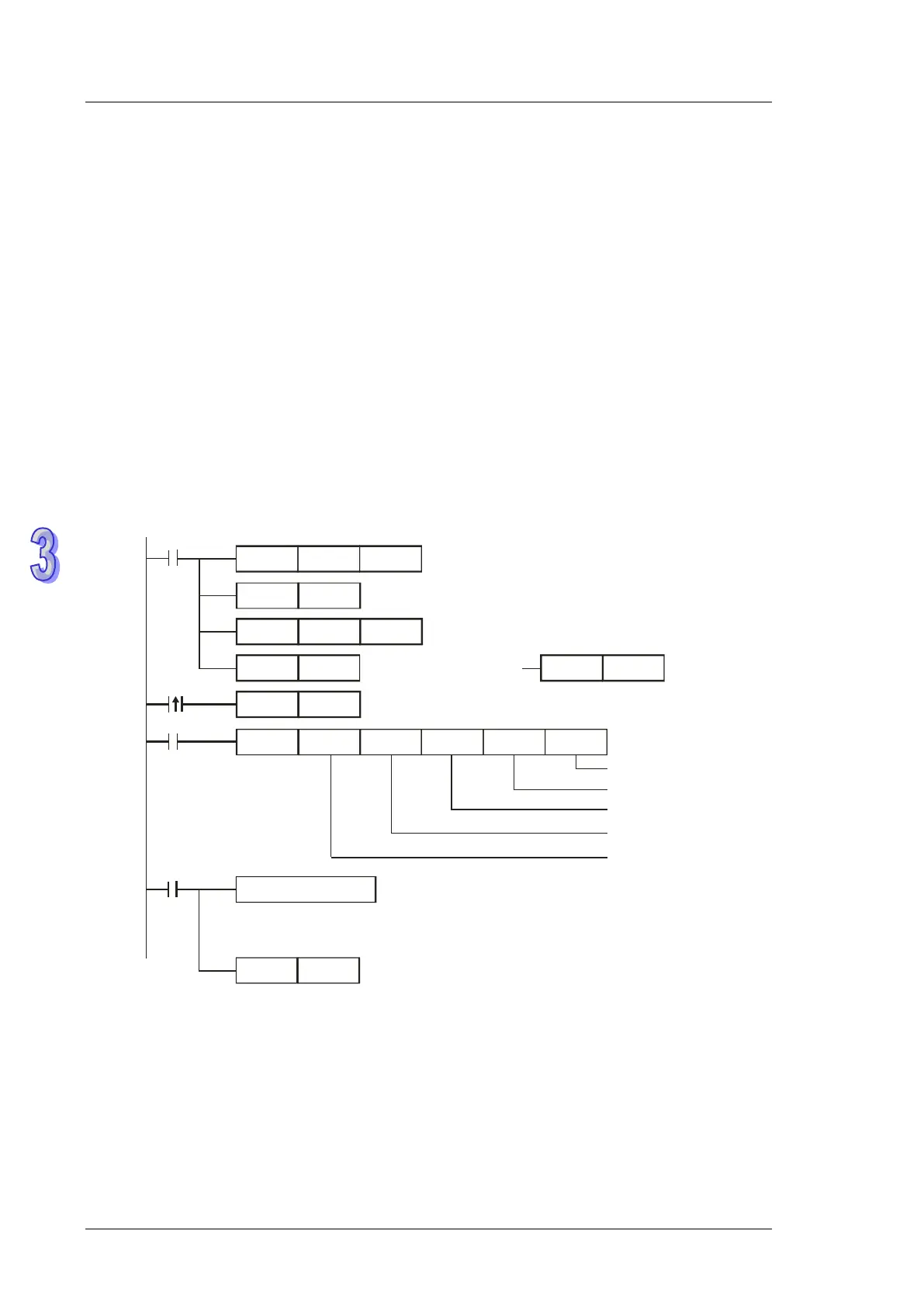
H87
MOV
M1002
D1109
SET
M1136
K100
MOV
D1252
MODRW
K5
K1
X0
H0500 D0
K1
Function Code K5:
Force ON/OFF bit device
Reserved
Force ON status (Set FF00H)
SET
X0
M1316
RST
M1320
SET
M1320
Connection device address: K1
Da ta a d dres s : Y0 = H0500
M1320 = OFF
ASCII mode
Set communication protocol as 9600,8,E,1
Re ta in communica tion protoc ol
Set receiving timeout as 100ms
Sending request
M1320 = ON
RTU mode
RST
M1318
M1318
Reset M1318
ASCII mode: No processing on received data .
RTU mode: No processing on received data .
Received data
Re ceiving comple te d
ASCII mode (COM3: M1320 = OFF, COM1: M1139 = OFF):
When X0 = ON, MODRW instruction executes the function specified by Function Code 05
PLC1 PLC2, PLC sends: “01 05 0500 FF00 6F”
PLC2 PLC1, PLC receives: “01 05 0500 FF00 6F”
(No data processing on received data)
 Loading...


