3. Instruction Set
Registers for received data (responding messages)
Data Address
Data content
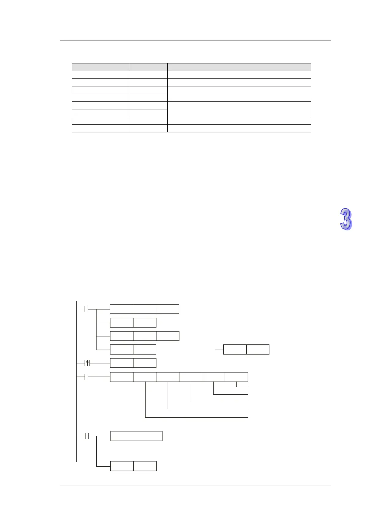
Program example 8: COM1 (RS-232) / COM3 (RS-485), Function Code H06
1. Function code K6 (H06): Write in single Word device.
2. Set the value to be written into VFD-B in the register specified by operand S.
3. PLC COM1/COM3 will not process the received data.
4. Take the connection between PLC (PLC COM3) and VFD-B for example, the tables below
explains the status when PLC COM3 writes in single Word device in VFD-B (M1320 = OFF,
ASCII Mode ), (M1320 = ON, RTU Mode)
If PLC applies COM1 for communication, the below program can be usable by changing:
a) D1109→D1036: communication protocol
b) M1136→M1138: retain communication setting
c) D1252→D1249: Set value for data receiving timeout
d) M1320→M1139: ASCII/RTU mode selection
e) M1316→M1312: sending request
f) M1318→M1314: receiving completed flag
H87
MOV
M1002
D1109
SET
M1136
K100
MOV
D1252
MODRW
K6
K1
X0
H2000 D50
K1
Connection device
address: K1
Function code: K6
Write in single Word data
Data address: H2000
Data register: D50=H1770
Da ta le n gth
SET
X0
M1316
RST
M1320
SET
M1320
M1320 = ON
ASCII mode
Set communication protocol as 9600,8,E,1
Re ta in commu nica tion s e tting
Set receiving timeout as 100ms
Sending request
M1320 = OFF
RTU mode
RST
M1318
M1318
Reset M1318
ASCII mode: No processing on received data .
RTU mode: No processing on received data .
Received data
Re ceiving comple te d
 Loading...


