3. Instruction Set
Program example 10: COM1 (RS-232) / COM3 (RS-485), Function Code H0F
1. Function code K15 (H0F): write in multiple bit devices. Up to 64 bits can be written
2. PLC1 connects to PLC2: (M1143 = OFF, ASCII mode), (M1143 = ON, RTU mode)
3. PLC COM1/COM3 will not process the received data.
4. Take the connection between PLC1 (PLC COM3) and PLC2 (PLC COM1) for example, the
tables below explain the status when PLC1 force ON/OFF Y0~Y17 of PLC2.
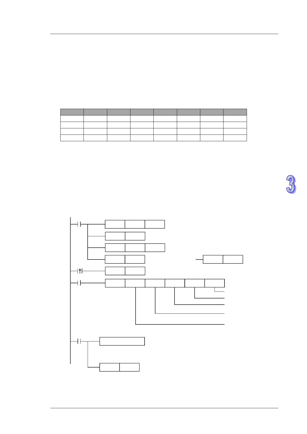
Set value: K4Y0=1234H
If PLC applies COM1 for communication, the below program can be usable by changing:
a) D1109→D1036: communication protocol
b) M1136→M1138: retain communication setting
c) D1252→D1249: Set value for data receiving timeout
d) M1320→M1139: ASCII/RTU mode selection
e) M1316→M1312: sending request
f) M1318→M1314: receiving completed flag
H87MOV
M1002
D1109
SET M1136
K100
MOV
D1252
Set communication protocol as 9600, 8, E, 1
Retain communication protocol
Set receiving timeout as 100ms
MODRW K15K1
X0
H0500 D0 K16
Connection device
address: K1
Function code: K15
Write in multiple bit devices
Data address: H0500
Data storing register
Data length(bit)
SET
X0
M1316
Sending request
M1320 = OFF
ASCII mode
RST
M1320
M1320 = ON
RTU mode
SET
M1320
RST M1318
M1318
Reset M1318
ASCII mode: No processing on received data .
RTU mode: No processing on received data .
Received data
Receiving completed