DVP-ES2/EX2/EC5/SS2/SA2/SX2/SE&TP Operation Manual - Programming
Program example 13: COM2 (RS-485)), Function Code H17
1. Function code K23 (H17): Data is read from multiple word devices and data is written into
multiple word devices. Data can be read from 16 word devices at most, and data can be
written into 16 word devices at most.
2. In the ASCII or RTU mode, the data received is stored in the registers starting from the
register indicated by the index value in S.
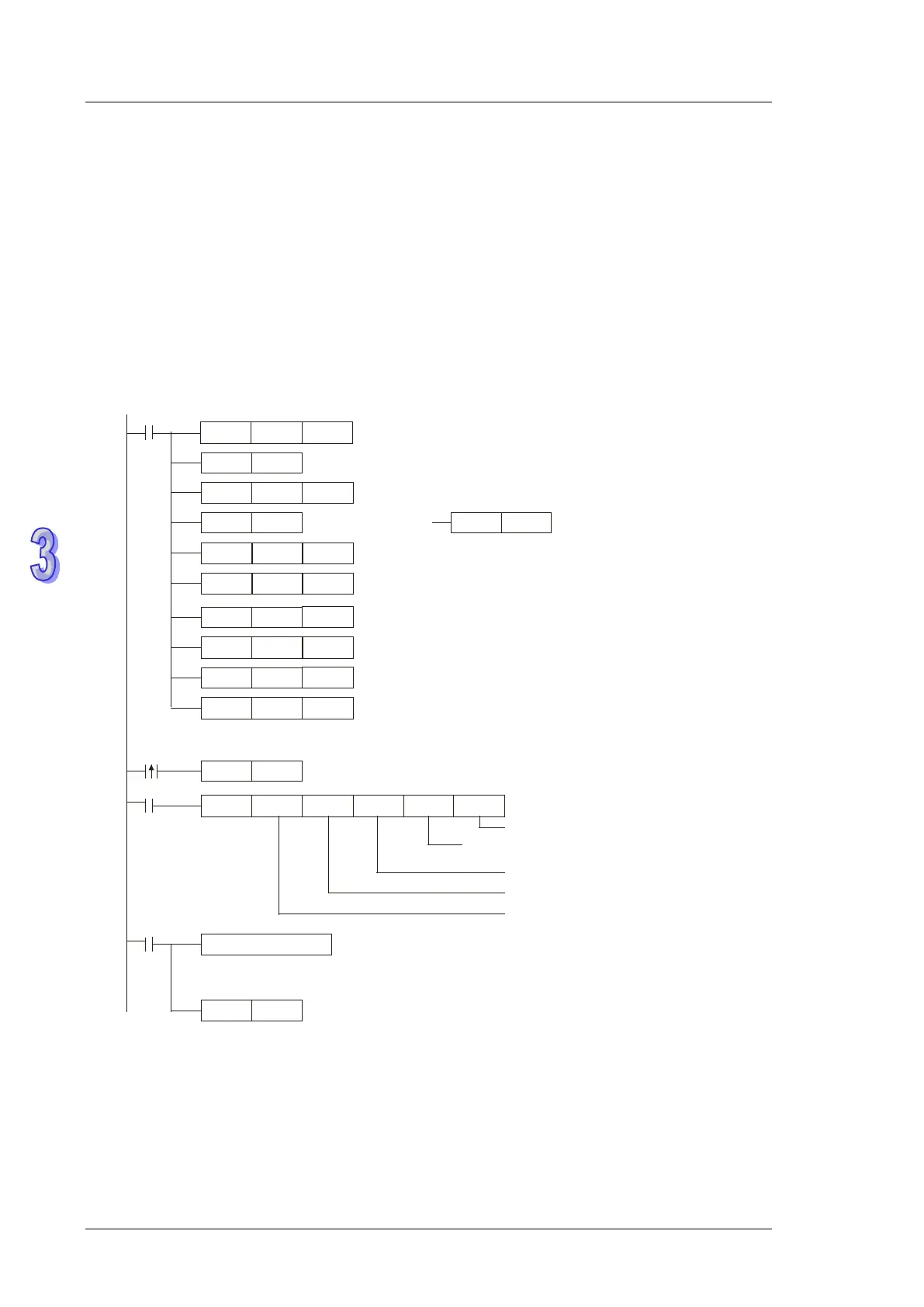
3. The connection between PLC-A (PLC COM2) and PLC-B:
Data is read from multiple word devices in PLC-B into PLC-A, and data is written into
multiple word devices in PLC-B from PLC-A. (M1143=OFF, ASCII Mode) (M1143=ON, RTU
Mode)
H87
MOV
M1002
D1120
SET
M1120
K100
MOV
D1129
RST
M1127
MODRW
K23
K1
X0
D0 D10
D20
M1127
SET
X0
M1122
RST
M1143
SET
M1143
H1100
MOV
D0
H1000
MOV
D1
K3000
MOV
D10
K4000
MOV
D11
K2
MOV
D20
K2
MOV
D21
Set communication protocol as 9600, 8, E, 1
Retain communication protocol
S
et communication timeout as 100ms
Connection device
address: K1
Function code: K23
The data is read from/written into multiple word devices.
Processing received data
ASCII mode : The received ASCII data is stored in the registers starting from D3000.
RTU mode : The received data is stored in the registers starting from D3000 in Hex value.
Reset M1127
Sending request
M
1143 = OFF
ASCII mode
M1143 = ON
RTU mode
The data is read from the address H1100.
The data is written into the address H1000.
The data is read into D3000.
The data is written from D4000.
The length of the data which is read is K2.
The length of the data which is written is K2.
D20: Length of the data read
D21: Length of the data written
D0: Address from which the data is read
D1: Address into which the data is written
D10:The index value indicates the register into which the data is read.
D11: The index value indicates the register from which the data is written.
• ASCII Mode (M1143=OFF)
When X0=ON, MODRW executes the function specified by the function ode H17.
PLC-A PLC-B, PLC-A sends: “01 17 1100 0002 1000 0002 04 1770 0012 06”
PLC-BPLC-A, PLC-A receives: “01 17 04 0100 1766 66”
Registers in PLC-A for received data (responding messages)