3. Instruction Set
Read/Write data (Settings)
K19(H13)
JOG Operation P4-05 040AH
S: Range:
1~5000, 4999, 4998, 0
K20(H14)
Auxiliary Function
(Servo ON/OFF)
P2-30 023CH
K21(H15)
P1-09 ~ P1-11 0112H ~ 0117H
S+0 ~ S+5: Range:
-60000~+60000
K22(H16)
P1-12 ~ P1-14
0118H ~ 011DH
S+0 ~ S+5: Range: -300~+300
K23(H17)
Write Register
(for mapping
P0-35 ~ P0-38
0046H~ 004DH
S+0 ~ S+7: Please refer to
explanations in ASDA-A2
manual.
6. For relative M flags and special D registers, please refer to explanations of API 80 RS
instruction.
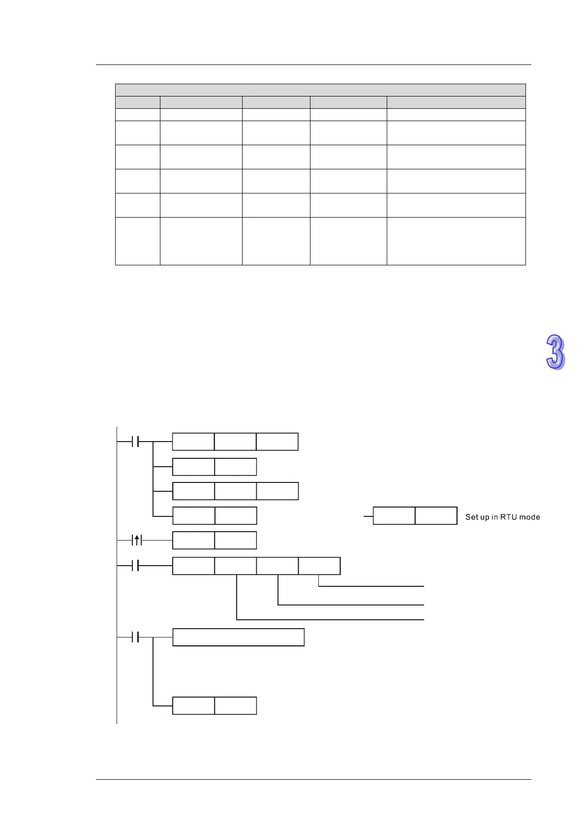
Program example 1: COM2 (RS-485)
1. When X0 = ON, PLC will send out communication commands by COM2 to read status of servo
drive.
2. When PLC received the feedback data from ASDA, M1127 will be active and the read data will
be stored in D0~D4.
H87MOV
M1002
D1120
SET
M1120
K100
MOV
D1129
RST M1127
ASDRW K0K1
X0
D0
ASDA address:
K1
Function Code: K0
Monitor ASDA status
Data Register
M1127
SET
X0
M1122
Set up in
ASCII mode
RST
M1143
SET
M1143
Reset communication completed flag M1127
Set communication protocol as 9600,8,E,1
Set time-out value as
100ms
ASCII mode:
Store the received data into specified registers D0~D4 in Hex
RTU mode:
Store the received data into specified registers D0~D4 in Hex
Sending request
Processing received data
Retain communication setting