3. Instruction Set
API
Mnemonic Operands Function
144 GPWM
General PWM output
Type
OP
Bit Devices Word devices Program Steps
X Y M S K H KnX
KnY
KnM
KnS
T C D E F
GPWM: 7 steps
SS2
SX2
SS2
SX2
SS2
SX2
Operands:
S
1
: Width of output pulse S
2
: Pulse output cycle (occupies 3 devices) D: Pulse output device
Explanations:
1. When GPWM instruction executes, pulse output will be executes on device specified by D
according to pulse output width S
1
and pulse output cycle S
2
.
2. S
1
: pulse output width. Range: t = 0~32,767ms.
3. S
2
: pulse output cycle. Range: T = 1~32,767ms, S
1
≦ S
2
.
4. S
2
+1 and S
2
+2 are system-defined parameters, please don’t use them.
5. D: pulse output device: Y, M and S.
6. When S
1
≦ 0, no pulse output will be performed. When S
1
≧ S
2
, the pulse output device remains
ON.
7. S
1
and S
2
can be modified when GPWM instruction is being executed
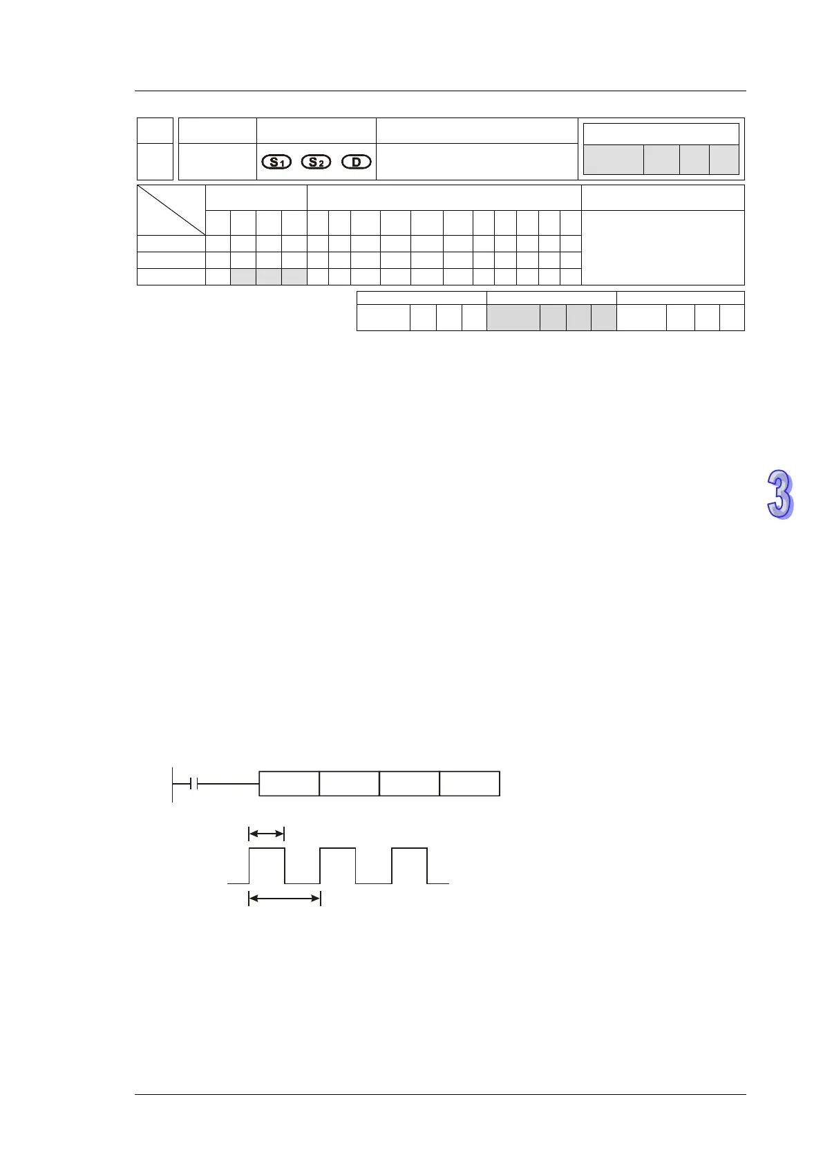
Program Example:
Assume D0 = K1000, D2 = K2000. When X0 = ON, Y20 will output pulses as the following diagram.
When X0 = OFF, Y20 output will be OFF.
t=1000ms
T=2000ms
Output Y20
Points to note:
1. The instruction operates by the scan cycle; therefore the maximum error will be one PLC scan
cycle. S
1
, S
2
and (S
2
- S
1
) should be bigger than PLC scan cycle, otherwise malfunction will
occur during GPWM outputs.
2. Please note that placing this instruction in a subroutine will cause inaccurate GPWM outputs.