3. Instruction Set
API
Mnemonic Operands Function
168 D
MVM P
Transfer Designated Bits
Type
OP
Bit Devices Word devices Program Steps
X Y M S K H KnX
KnY
KnM
KnS
T C D E F
MVM, MVMP: 7 steps
DMVM,DMVMP:
13 steps
SS2
SX2
SS2
SX2
SS2
SX2
Operands:
S
1
: Source device 1 S
2
: Bits to be masked (OFF) D: D =( S
1
& S
2
) | ( D & ~ S
2
)
Explanations:
1. The instruction conducts logical AND operation between S
1
and S
2
first, logical AND operation
between D and ~S
2
secondly, and combines the 1
st
and 2
nd
results in D by logical OR
operation.
2. Rule of Logical AND operation: 0 AND 1 = 0, 1 AND 0 = 0, 0 AND 0 = 0, 1 AND 1 = 1
3. Rule of Logical OR operation: 0 OR 1= 1, 1 OR 0 = 1, 0 OR 0 = 0, 1 OR 1 = 1.
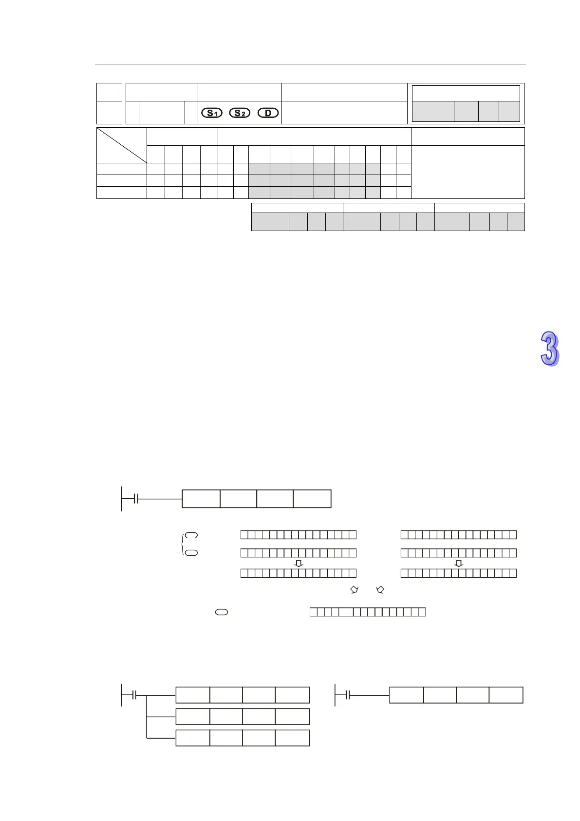
Program Example 1 :
When X0 = ON, MVM instruction conducts logical AND operation between 16-bit register D0 and
H’FF00 first, logical AND operation between D4 and H’00FF secondly, and combines the 1
st
and 2
nd
results in D4 by logical OR operation.
0 1 0 1 0 1 0 11
0
1 0 1 0 1 0
1 1 1 1 1 1 0 0 0 0 01 1 0 0 0
1
0 1 1 0 0 0 0 0 0 0 0 0
0
1 0
AND
b15 b0
S
1
S2
D
D0=HAA55
HFF00
D4=HAA34
HAA00
0 0 1 1 0 1 0 00
0
0 1 0 0 1 0
0 0 0 0 0 0 1 1 1 1 10 0 1 1 1
0
0 0 0 0 0 0 0 1 1 0 0 0
0
0 1
AND
b15 b0
D4=H1234
H00FF
H0034
OR
1
0 1 1 0 0 0 0 1 1 0 0 0
0
1 1
b15
Before the execution
After the execution
Program Example 2 :
Simplify instructions:
WAND
X0
HFF00
D110 D110
MVM
X0
D110
HFF00 D120
WAND H00FF D120 D120
WOR D100 D120 D120
=