3. Instruction Set
API
Mnemonic Operands Function
207 CSFO
Catch speed and
proportional output
Type
OP
Bit Devices Word devices Program Steps
X Y M S K H KnX
KnY
KnM
KnS
T C D E F
CSFO: 7 steps
SS2
SX2
SS2
SA2
SX2
SE
SS2
SX2
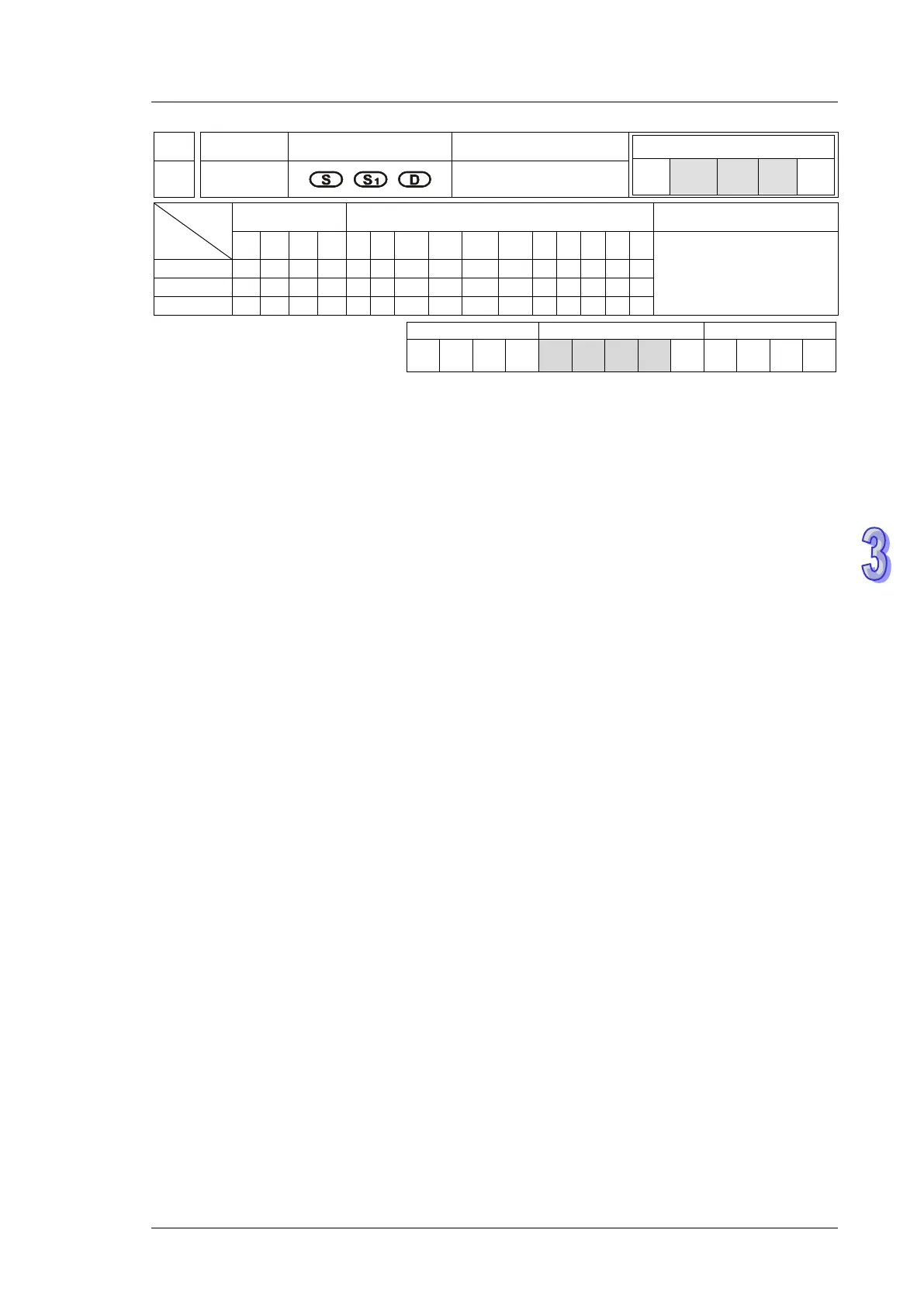
Operands:
S: Source device of signal input (Only X0~X3 are available) S
1
: Sample time setting and the
input speed information D: Output proportion setting and output speed information
Explanations:
1. When S specifies X0, PLC only uses X0 input point and its associated high speed pulse output:
Y0, in this case Y1 is normal output point. When S specifies X1, PLC uses X0 (A phase) and X1
(B phase) input points and their associated output: Y0 (Pulse) / Y1 (Dir). When S specifies X2,
PLC only uses X2 input point and its associated high speed pulse output: Y2, in this case Y3 is
normal output point. When S specifies X3, PLC uses X2 (A phase) and X3 (B phase) input
points and their associated output: Y2 (Pulse) / Y3 (Dir).
2. The execution of CSFO requires hardware high speed counter function as well as the high
speed output function. Therefore, when program scan proceeds to CSFO instruction with high
speed counter input points (X0, X1) or (X2, X3) enabled by DCNT instruction, or high speed
pulse outputs (Y0, Y1) or (Y2, Y3) enabled by other high speed output instructions, CSFO
instruction will not be activated.
3. If S specifies X1 / X3 with 2-phase 2 inputs, the counting mode is fixed as one time frequency.
4. During pulse output process of Y0 or Y2, special registers (D1031, D1330 / D1337, D1336)
storing the current number of output pulses will be updated when program scan proceeds to this
instruction.
5. S
1
occupies consecutive 4 16-bit registers. S
1
+0 specifies the sampling times, i.e. when S
1
+0
specifies K1, PLC catches the speed every time when 1 pulse is outputted. Valid range for S
1
+0
in 1-phase 1-input mode: K1~K100, and 2-phase 2-input mode: K2~K100. If the specified value
exceeds the valid range, PLC will take the lower/upper bound value as the set value. Sample
time can be changed during PLC operation, however the modified value will take effect until
program scan proceeds to this instruction. S
1
+1 indicates the latest speed sampled by PLC
(Read-only). Unit: 1Hz. Valid range: ±10kHz. S
1
+2 and S
1
+3 indicate the accumulated number
of pulses in 32-bit data (Read-only).
 Loading...