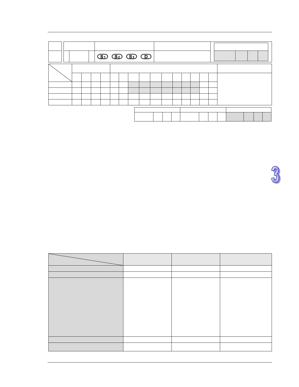
3. Instruction Set
API
Mnemonic Operands Function
156 D
ZRN
Zero return
Type
OP
Bit Devices Word Devices Program Steps
X Y M S K H KnX
KnY
KnM
KnS
T C D E F
DZRN: 17 steps
SS2
SX2
SS2
SX2
SS2
SX2
Operands:
S
1
: Target frequency for zero return S
2
: JOG frequency for DOG S
3
: input device for DOG D:
Pulse output device
Explanations (Applicable to ES2, EX2, SS2, SA2, SE, SX2 Series):
1. S
1
(zero return speed): ranging from 6 Hz to 100k Hz; S
2
(JOG speed for DOG) has to be lower
than S
1.
And S
2
also refers to the start frequency.
2. S
3
and D operands have to be used as an input/output set according to the table below, i.e. when
S
3
is specified as X4, D has to be specified as Y0; also when S
3
is specified as X6, D has to be
specified as Y2.
3. M1307 enables (ON) / disables (OFF) left limit switch of CH0 (Y0, Y1) and CH1 (Y2, Y3). M1307
has to be set up before the instruction executes. M1305 and M1306 can reverse the pulse output
direction on Y1 and Y3 and have to be set up before instruction executes. Associated left limit
switch for CH0 (Y0, Y1) is X5; associated left limit switch for CH1 (Y2, Y3) is X7. All functions, input
points and output points are arranged as follows:
CH0(Y0,Y1) CH1(Y2,Y3) Remark
Left limit switch (M1307 = ON)
triggerred by a rising-edge
signal or a falling-edge signal.
(OFF: Rising-edge signal; ON:
Falling-edge signal)
(ES2/EX2/ES2-C V3.20 and
above/SA2 V2.80 and
above/SX2 V2.60 and
above/SS2 V3.0 and above/SE
M1584 M1585
Reverse pulse output direction
Zero point stopping position M1106 M1107 Please refer to point