3. Instruction Set
that the pulses are output in the positive direction. When D1312 is a negative value (the minimum
value is -30000), it indicates that the pulses are output in the negative direction. For example, if
D1312 is k-100, it means that DOG stops immediately after DOG leaves DOG switch and another
100 pulses will be output in the negative direction with JOG frequency. Please refer to state 6 for
the timing diagram of this function. (The function supports ES2/EX2 series of V1.40 or above, and
SS2/SX2 series of V1.20 or above.)
11. This instruction should not be used in the interrupt programs or subroutine that only be called once
or used with auto-reset flags.
Explanations (Applicable to EC5 Series):
1. S
1
(zero return speed): ranging from 6 Hz to 100k Hz; S
2
(JOG speed for DOG) has to be lower
than S
1.
And S
2
also refers to the start frequency.
2. S
3
and D operands have to be used as an input/output set according to the table below, i.e. when
S
3
is specified as X4, D has to be specified as Y0; also when S
3
is specified as X6, D has to be
specified as Y2. When S
3
is specified as X14, D has to be specified as Y4. When S
3
is specified as
X16, D has to be specified as Y6.
3. M1307 enables (ON) / disables (OFF) left limit switch of CH0 (Y0, Y1), CH1 (Y2, Y3), CH2 (Y4,
Y5), and CH3 (Y6, Y7). M1305, M1306, M1532, and M1533 have to be set up before the
instruction executes. M1305 and M1306 can reverse the pulse output direction on Y1, Y3, Y5, Y7
and have to be set up before instruction executes. Associated left limit switch for CH0 (Y0, Y1) is
X5, CH1 (Y2, Y3) is X7, CH2 (Y4, Y5) is X15, and CH3 (Y6, Y7) is X17. All functions, input points
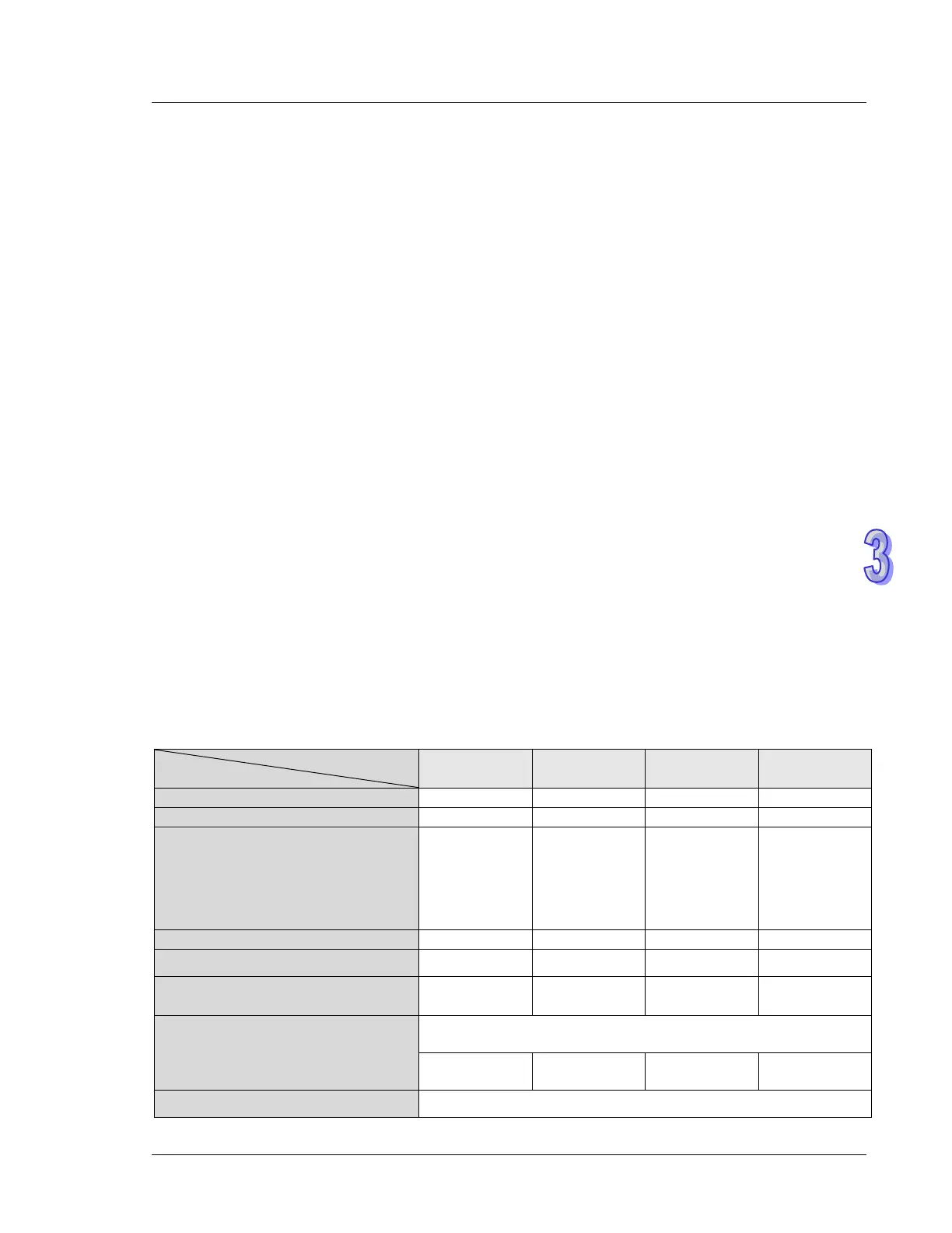
and output points are arranged as follows:
CH0 (Y0,Y1) CH1 (Y2,Y3) CH2 (Y4,Y5) CH3 (Y6,Y7)
Left limit switch (M1307 = ON)
The left limit switch is triggerred by
a rising-edge signal or a
falling-edge signal. (OFF:
Rising-edge signal; ON:
Falling-edge signal)
M1584 M1585 M1586 M1587
Reverse pulse output direction
Zero point selection M1106 M1107 M1588 M1589
M1346=On
Start output clear signals
Y10 Y11 Y12 Y13
D1312 != 0
M1308 = Off (seeking Z-phase signal)
X2 X3 NA
#
NA
#
D1312 != 0 M1308 = On (outputting the designated number of pulses)