3. Instruction Set
that the pulses are output in the positive direction. When D1312 is a negative value (the minimum
value is -30000), it indicates that the pulses are output in the negative direction. For example, if
D1312 is k-100, it means that DOG stops immediately after DOG leaves DOG switch and another
100 pulses will be output in the negative direction with JOG frequency. Please refer to state 6 for
the timing diagram of this function.
12. This instruction should not be used in the interrupt programs or subroutine that only be called once
or used with auto-reset flags.
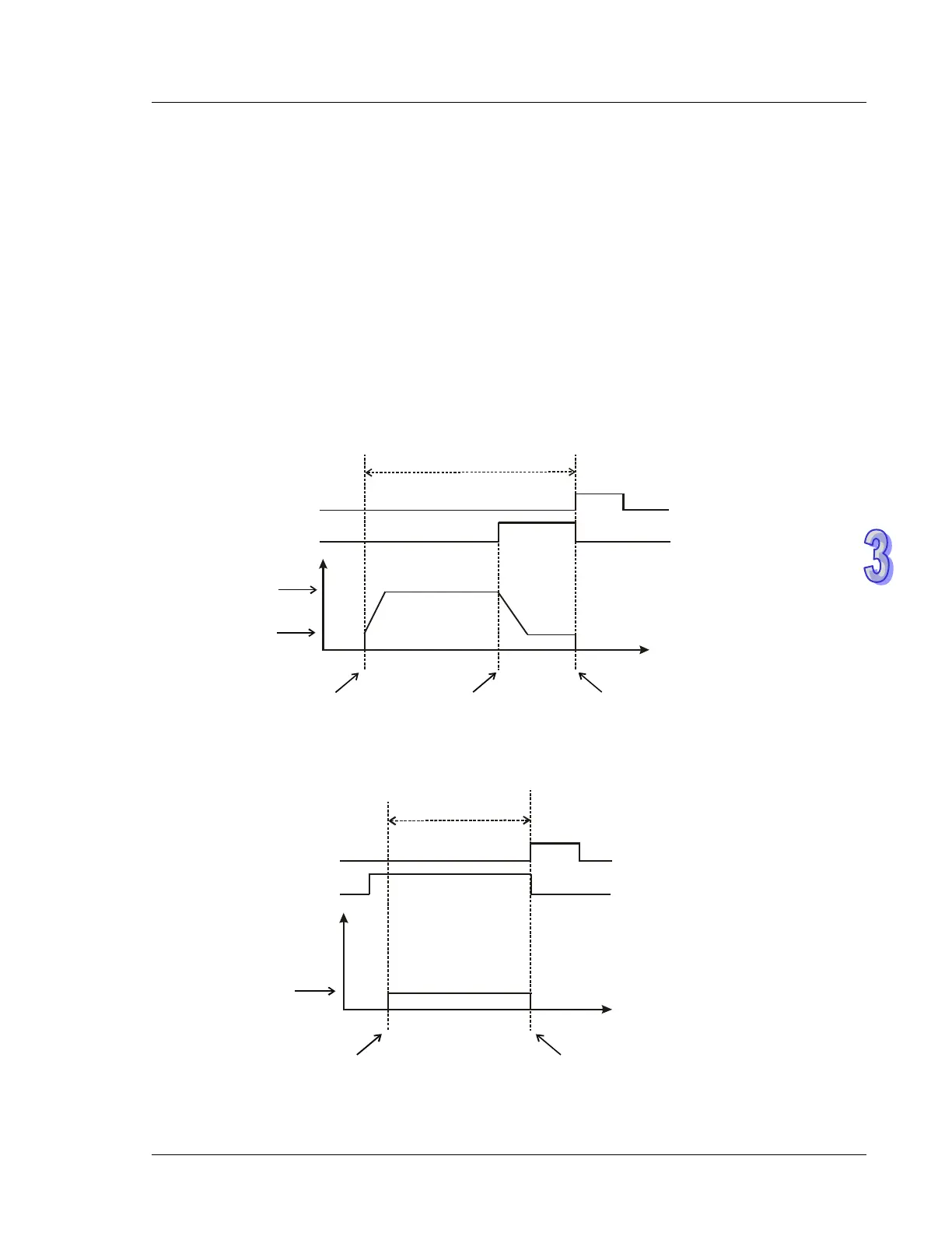
Timing Diagram:
State 1: Current position at right side of DOG switch, pulse output in reverse, limit switch disabled.
Output in reverse
OFF
ON
End flag
M
1029/M1102
DOG switch: X4/X6
Freq.
Target freq.
JOG freq.
Time
Start
Meet DOG switch DOG switch OFF
ON
OFF
State 2: DOG switch is ON, pulse output in reverse, limit switch disabled.
Off
On
On
Off
Output in reverse
End flag
M1029/M1102
DOG switch: X4/X6
Freq.
JOG freq.
Time
Start
DOG switch OFF