3. Instruction Set
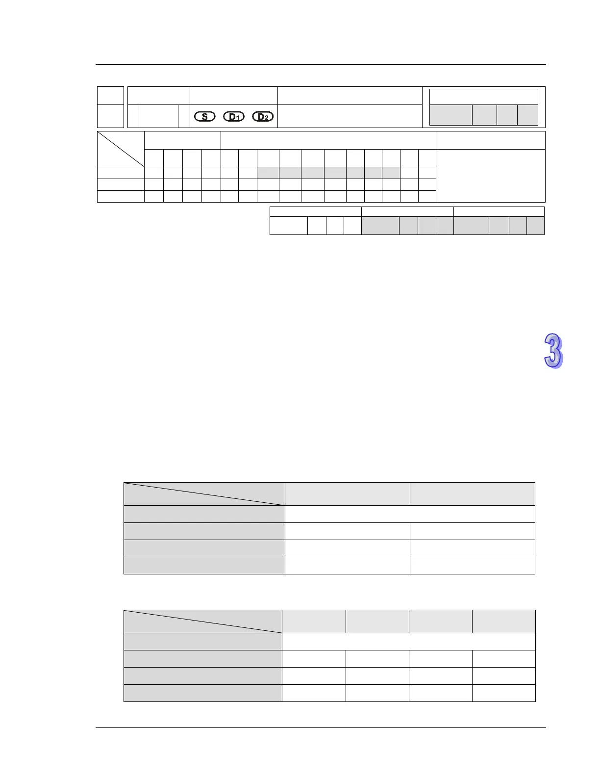
API
Mnemonic Operands Function
157 D
PLSV
Adjustable Speed Pulse
Output
Type
OP
Bit Devices Word Devices Program Steps
X Y M S K H KnX
KnY
KnM
KnS
T C D E F
PLSV: 7 steps
DPLSV: 13 steps
SS2
SX2
SS2
SX2
SS2
SX2
Operands:
S: Pulse output frequency D
1
: Pulse output device (Y0, Y2, Y4, Y6) D
2
: Direction signal output
Explanations:
1. The instruction only supports the pulse output type: Pulse + Direction.
2. S is the designated pulse output frequency. “+/-” signs indicate forward/reverse output direction.
The frequency can be changed during pulse output. However, if the specified output direction is
diferent from the current output direction, the instruction will stop for 1 scan cycle then restart with
the changed frequency.
3. The operation of D
2
corresponds to the “+” or “-“ of S. When S is “+”, D
2
will be OFF; when S is “-“,
D
2
will be ON.
4. M1305 and M1306 can change the output direction of CH0/CH1 set in D
2
. When S is “-“, D
2
will be
ON, however, if M1305/M1306 is set ON before instruction executes, D
2
will be OFF during
execution of instruction. For series, other than EC5 Series.
CH0 CH1
Pulse output frequency (S) -100,000Hz ~ +100,000Hz
Pulse output device (D
1
) Y0 Y2
Directon signal ouptut (D
2
) Y1 Y3
Reverse pulse output direction M1305 M1306
For EC5 Series
CH0 CH1 CH2 CH3
Pulse output frequency (S) -50,000 Hz ~ +50,000 Hz
Pulse output device (D
1
) Y0 Y2 Y4 Y6
Directon signal ouptut (D
2
) Y1 Y3 Y5 Y7
Reverse pulse output direction M1305 M1306 M1532 M1533