3. Instruction Set
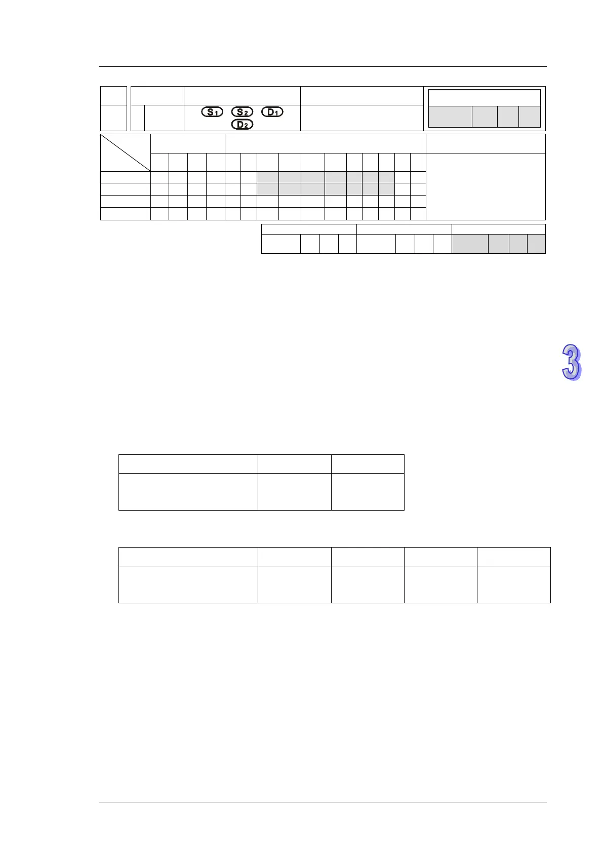
API
Mnemonic
Operands Function
Controllers
158 D
DRVI
Relative Position
Control
Type
OP
Bit Devices Word devices Program Steps
X Y M S K H KnX
KnY
KnM
KnS
T C D E F
DDRVI: 17 steps
SS2
SX2
SS2
SX2
SS2
SX2
Operands:
S
1
: Number of pulses (relative positioning) S
2
: Pulse output frequency D
1
: Pulse output device
D
2
: Direction signal output
Explanations (Applicable to ES2, EX2, SS2, SA2, SE, SX2 Series):
1. The instruction only supports the pulse output type: Pulse + Direction.
2. S
1
is the number of pulses (relative positioning). Available range: -2,147,483,648 ~
+2,147,483,647. “+/-” signs indicate forward and reverse direction.
3. S
2
is the pulse output frequency. Available range: 6 ~ 100,000Hz.
4. D
1
is the pulse output device. It can designate CH0 (Y0) and CH1 (Y2).
5. D
2
is the direction signal output device. It can designate CH0 (Y1) and CH1 (Y3).
Pulse output device (D
1
) Y0 Y2
Corresponding direction
signal output device (D
2
)
Y1 Y3
6. ES2/EX2: V3.46, ES2-C: V3.48, ES2-E: V1.00, 12SE: V2.02, 26SE: V1.0 and later versions
support the settings in D
1
and D
2
as shown below.
Pulse output device (D
1
) Y0 Y1 Y2 Y3
Corresponding direction
signal output device (D
2
)
Y4 Y5 Y6 Y7
7. The operation of D
2
corresponds to the “+” or “-“ of S. When S is “+”, D
2
will be OFF; when S is
“-“, D
2
will be ON. D
2
will not be OFF immediately after pulse output completion and will be OFF
when the drive contact is OFF.
8. The set value in S
1
is the relative position of
- current position (32-bit data) of CH0 (Y0, Y1) which is stored in D1031(high), D1030 (low)
- current position (32-bit data) of CH1 (Y2, Y3) which is stored in D1337(high), D1336 (low).
In reverse direction pulse output, value in (D1031, D1330) and (D1336, D1337)
decreases.