3. Instruction Set
d. Set P3-01 to 0400 and the baud rate of the servo for CANopen communication to 1.0
Mbit/S. The baud rate must be the same as that of the PLC. For firmware V3.48 or earlier
versions, the baud rate is fixed to 1.0Mbit/S. For firmware V3.60 or later, you can set the
baud rate through CANopen Builder.
e. Set a station address for every servo, based on the number of servos. Set P3-00 of each
servo to 1, 2, and 3 in order. You can set a maximum of eight servos.
f. Power the servo off and back on again.
g. Begin operation after the basic setting is complete.
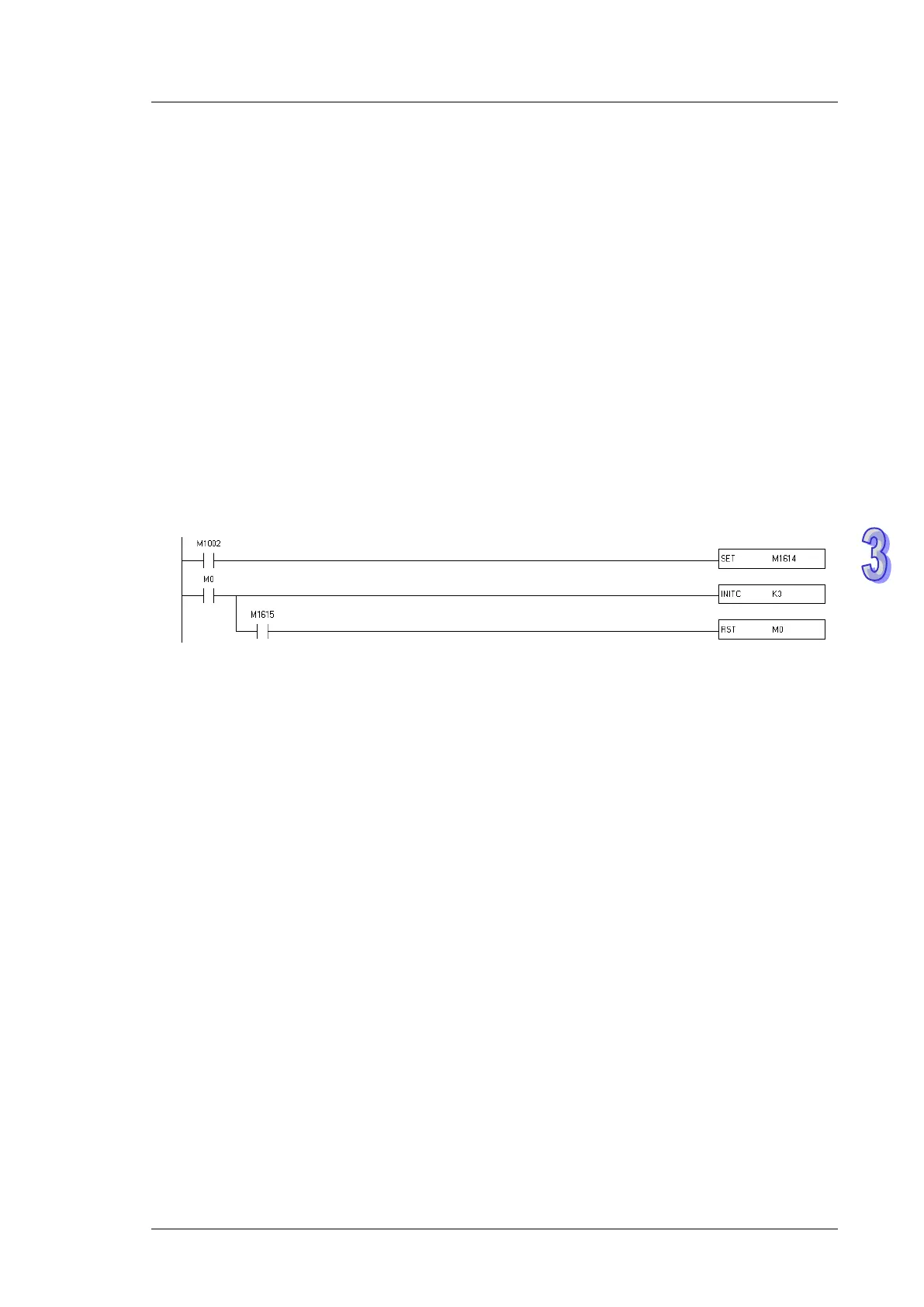
3. Download the sample program and set M1614 to ON to enable Delta servo drive function.
The instruction initializes the servos at station addresses 1–3. When M1615 is ON, the
initialization is complete. When the servo enters CANopen mode successfully, CO-LD
information is displayed.
4. For firmware V3.43-3.47, you can set the DI values in the initialization process, including
DI1~DI4 (P2-10=23, P2-11=22, P2-12=21, P2-13=24 ). For firmware V3.48 or later, this
function is cancelled. You can use actual values according to your needs or use default
values.
5. The following list shows the settings to initialize a servo drive for firmware V3.48 or later.
a. Set P2-30 (auxiliary function) to 5 to indicate that the servo does not need to store the
settings in EEPROM permanently. This can prolong the servo life span. (for firmware
V3.60 or later).
b. Reset P6-02 (PATH#1) to 0 and P6-06 (PATH#3) to 0. This indicates that PATH#1 & #3 in
PR mode are both cleared.
c. Set P3-06 (SDI source) to 16#0100. This indicates that DI1–DI8 are controlled by the
hardware, EDI9 is controlled by the software, and EDI10–EDI14 are controlled by the
hardware.
d. Reset P4-07 (SDI status controlled manually) to 0.
e. Set P2-36 (EDI9) to 16#0101. This indicates that the function of EDI9 is set to Servo ON.