3. Instruction Set
5. For the index addresses and subindex addresses of Delta servo and AC motor drive, refer to
the explanation of the COPRW instruction. In principle, the parameter values of Delta servo
and AC motor drive are both16-bit or 32-bit values including floating point numbers. If you
need write an 8-bit value, use the COPRW instruction.
6. D is the communication completion flag. D will turn on after the sending of multiple
communication messages is complete.
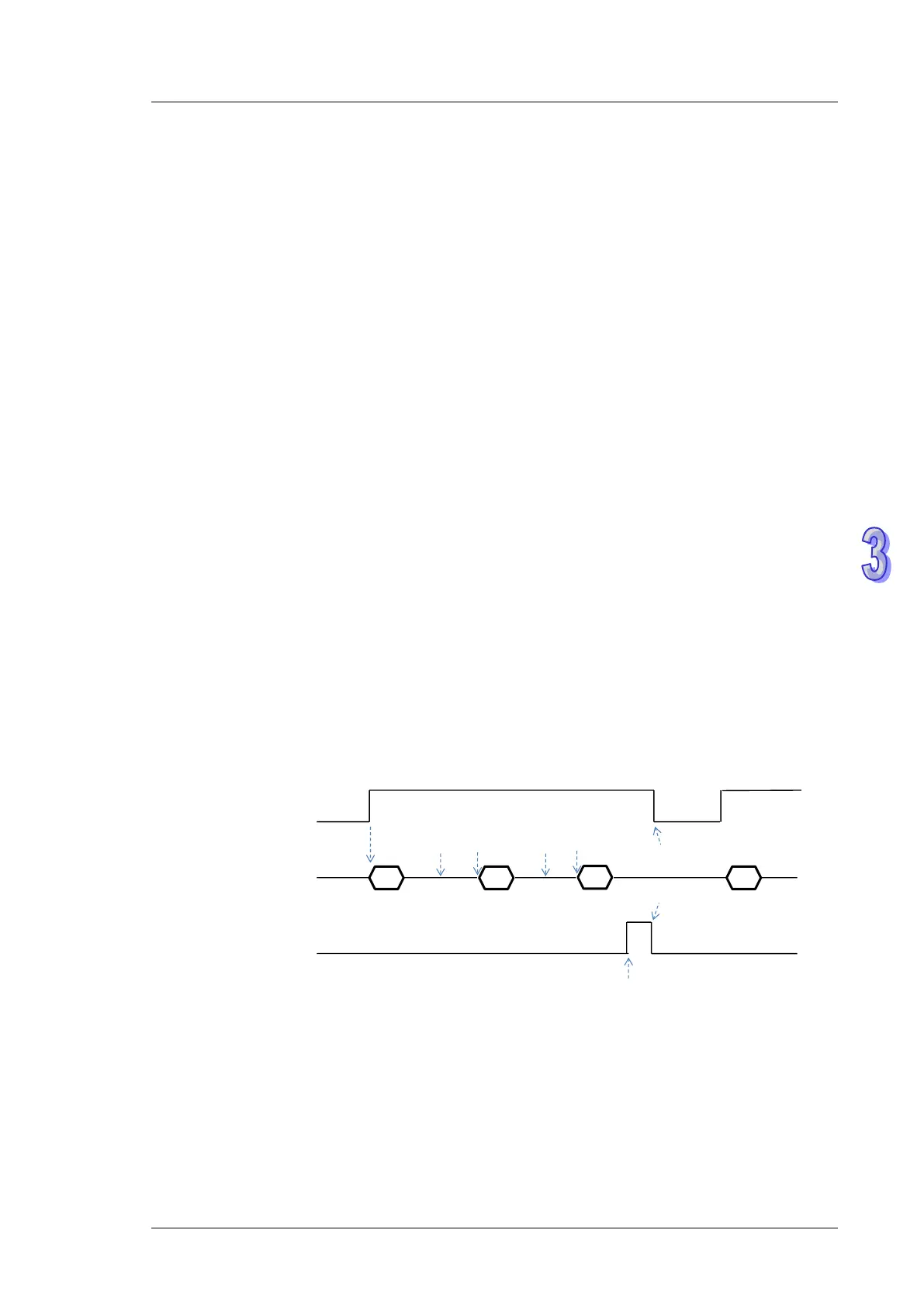
See the detailed sending process and sequence diagram below.
The COPWL instruction is enabled and starts to send data.
After the COPWL instruction sends one piece of message, the next PLC instruction
continues to execute.
As the COPWL instruction is scanned once again and the prior message has been received
by the slave, the COPWL instruction sends the next message.
When the last written-data sending is done, the instruction will set the completion flag to
ON.
When the completion flag turns on, the COPWL instruction need be disabled by manual so
that the subsequent COPWL or COPRW instruction can continue to work.
Note: When you disable the instruction, the completion flag will be automatically cleared
accordingly.
1
disable
enable
disable
COPWL
S
2
2
D
3
1
enable
Note: The sequence diagram above shows the sending of 3 pieces of written data.
7. After the instruction is enabled, wait until the writing is complete and then disable the
instruction. If there is a communication error in the execution, shoot the trouble and then
re-enable the instruction to write all data.