2. Programming Concepts
D
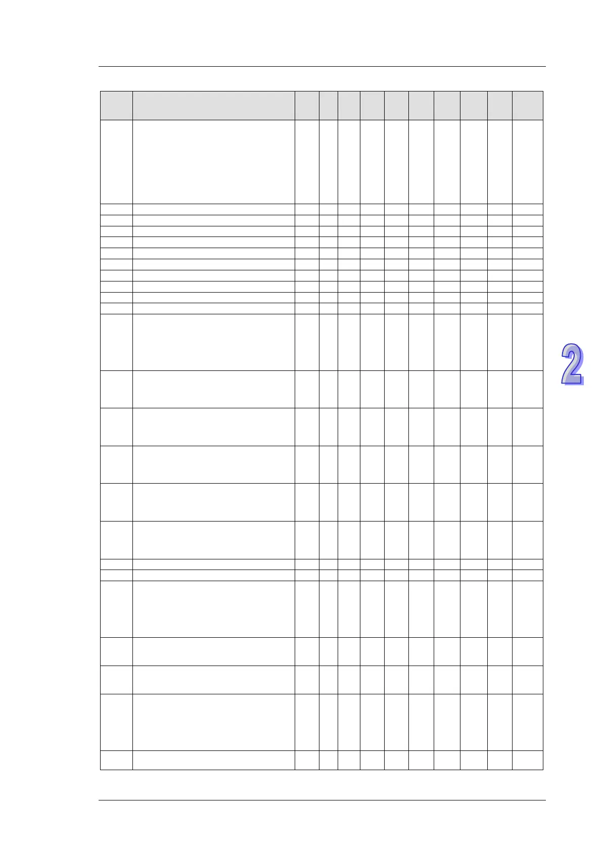
Content
EX2
SS2
SA2
SE
SX2
Attrib.
Latch
-ed
Default
D1038
1. Delay time setting for data response
when PLC is SLAVE in COM2 / COM3 RS-
485 communication. Range: 0 ~ 20 (unit:
0.1ms). Refer to section 2.16 the
description on D1038 for more information.
2. By using PLC LINK in COM2 (RS-485),
D1038 can be set to send next
communication data with delay. Range: 0 ~
10,000 (Unit: one scan cycle)
○ ○ ○ ○
- - - R/W NO 0
○
○
○
○
No. of the 1st step point which is ON.
○
○
○
○
No. of the 2nd step point which is ON
○
○
○
○
No. of the 3rd step point which is ON.
○
○
○
○
No. of the 4th step point which is ON
○
○
○
○
No. of the 5th step point which is ON.
○
○
○
○
No. of the 6th step point which is ON
○
○
○
○
No. of the 7th step point which is ON.
○
○
○
○
No. of the 8th step point which is ON
○
○
○
○
○
○
○
○
D1050
↓
D1055
Processing MODRD communication data
The PLC automatically converts the data in
D1070~D1085 in the ASCII mode into
hexadecimal values, or combines two
lower 8 bits in the RTU mode into 16 bits in
○ ○ ○ ○
0 - - R NO 0
D1056*
Low word of X0’s input pulse frequency
(Unit: 0.001Hz) It is used with M1357,
available for
ES2/EX2: V3.22, ES2-C:
V3.68, SA2: V3.02, SX2: V2.66 or later.
ES2/
EX2
╳
SA2
○
0 0 - R NO 0
D1057*
High word of X0’s input pulse frequency
(Unit: 0.001Hz) It is used with M1357,
available for
ES2/EX2: V3.22, ES2-C:
V3.68, SA2: V3.02, SX2: V2.66 or later.
ES2/
EX2
╳
SA2
○
0 0 - R NO 0
D1058*
Low word of X1’s input pulse frequency
(Unit: 0.001Hz) It is used with M1358,
available for
ES2/EX2: V3.22, ES2-C:
V3.68, SA2: V3.02, SX2: V2.66 or later.
ES2/
EX2
╳
SA2
○
0 0 - R NO 0
D1059*
High word of X1’s input pulse frequency
(Unit: 0.001Hz) It is used with M1358,
available for
ES2/EX2: V3.22, ES2-C:
V3.68, SA2: V3.02, SX2: V2.66 or later.
ES2/
EX2
╳
SA2
○
0 0 - R NO 0
D1062*
Average number of times an analog signal
is input to the EX2/SX2 series PLC
The default value is K10 for EX2 version
ES2/
EX2
╳ ╳ ○
2 - - R/W YES 2
Error code for program execution error
○
○
○
○
Address of program execution error
○
○
○
○
D1070
↓
D1085
Feedback data (ASCII) of Modbus
communication. When PLC’s RS-485
communication instruction receives
feedback signals, the data will be saved in
the registers D1070~D1085. Usres can
check the received data in these registers.
○ ○ ○ ○
0 - - R NO 0
D1086
High word of the password in DVP-PCC01
(displayed in hex according to its ASCII
○ ○ ○ ○
0 - - R/W NO 0
D1087
Low word of the password in DVP-PCC01
(displayed in hex according to its ASCII
○ ○ ○ ○
0 - - R/W NO 0
D1089
↓
D1099
Sent data of Modbus communication.
When PLC’s RS-485 communication
instruction sends out data, the data will be
stored in D1089~D1099. Users can check
the sent data in these registers.
○ ○ ○ ○
0 - - R NO 0
D1109* COM3 (RS-485) Communication protocol
╳ ○ ○
H’86 - - R/W NO H’86