DVP-ES2/EX2/EC5/SS2/SA2/SX2/SE&TP Operation Manual - Programming
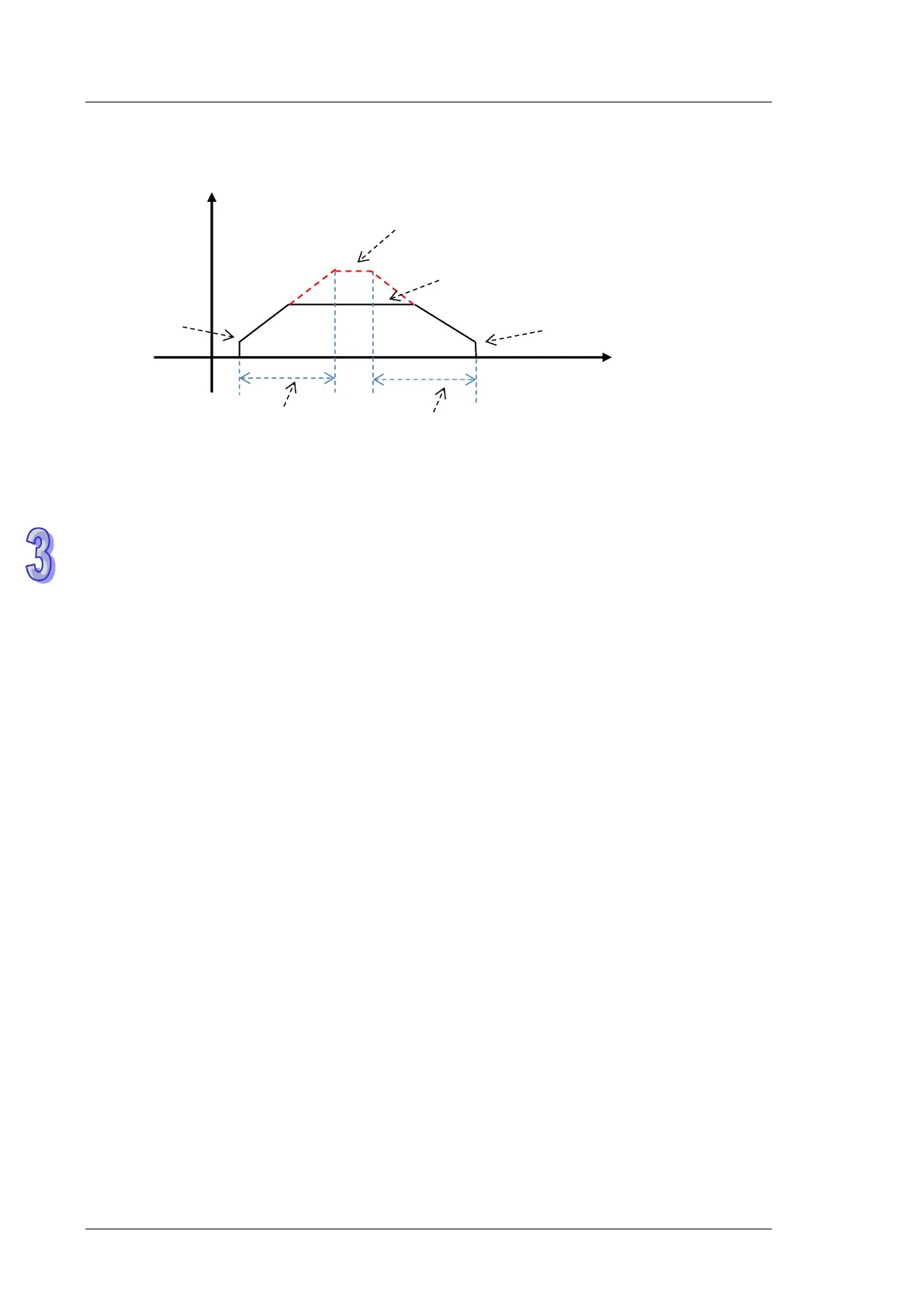
11. Illustration of the acceleration and deceleration curve of the DPUDRI instruction
: Maximum output frequency value. Refer to the setting in the DPUCONF instruction for the
parameter setting. Alternatively, set the parameter value through HWCONFIG.
: The target frequency specified by the PU module output instruction. The target frequency
output must not exceed the maximum output frequency. If the maximum output frequency is
exceeded, the maximum output frequency is regarded as the output frequency.
: Starting/ending output frequency value. Refer to the setting in the DPUCONF instruction for
the parameter setting. Alternatively, set the parameter value through HWCONFIG.
: The acceleration time value. Refer to the setting in the DPUCONF instruction for the
parameter setting. Alternatively, set the parameter value through HWCONFIG.
: The deceleration time value. Refer to the setting in the DPUCONF instruction for the
parameter setting. Alternatively, set the parameter value through HWCONFIG.
The acceleration and deceleration that the PU module controls is performed according to the
fixed slope. So the actual acceleration time and deceleration time change based on the output
target frequency. The formula for calculation of acceleration rate and deceleration rate are
respectively shown as follows.
(Max. output frequency - starting frequency)/acceleration time;
(Max. output frequency - ending frequency)/deceleration time.